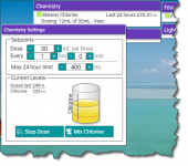
After noticing that I have two extra valve outputs, but no extra relays, I thought maybe I could use a valve output to control my Stenner pump. That way I could schedule my dosing cycle along with a set filter pump speed as a feature circuit and set the dose time accurately in one place instead of needing to use an extra timer.
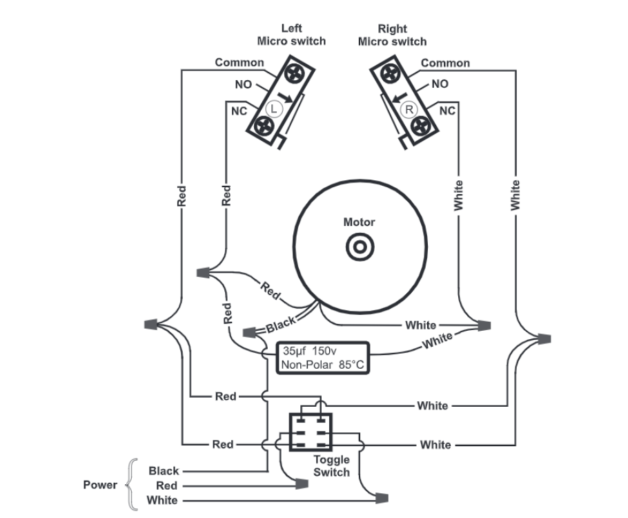
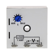
The Stenner Econ FP seems like it could fit the bill nicely. It can activate based on a dry contact OR a 12-24 vac or vdc signal. Does anyone know what the Intellicenter's 3 pin valve actuator connector actually outputs when a valve is active vs inactive? I know my Intellivalve's are always getting power, so I assume two of the wires are 12 or 24 vdc and a ground. Maybe the 3rd wire gets 12v or 24v applied when the valve is supposed to be "on" or activated out of home position. I can test this with a multimeter but need to track down the right spare connector to avoid shorting anything (dont want to cut into my nice new Intellivalves) - I figured I would ask if anyone knows how these valve ports actually work at the basic electrical level.
The Stenner Econ FP seems like it could fit the bill nicely. It can activate based on a dry contact OR a 12-24 vac or vdc signal. Does anyone know what the Intellicenter's 3 pin valve actuator connector actually outputs when a valve is active vs inactive? I know my Intellivalve's are always getting power, so I assume two of the wires are 12 or 24 vdc and a ground. Maybe the 3rd wire gets 12v or 24v applied when the valve is supposed to be "on" or activated out of home position. I can test this with a multimeter but need to track down the right spare connector to avoid shorting anything (dont want to cut into my nice new Intellivalves) - I figured I would ask if anyone knows how these valve ports actually work at the basic electrical level.