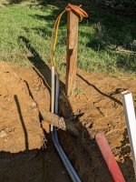
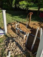
The issue they seem to be having is when the valve on #8 is closed, the vacuum port outputs a good pressure but when it's open, they get very little pressure from the vacuum port. Based on what you're saying, when #8 valve is closed this would make that return flow backwards and suction from the return. When the 8 valve is open and they're not getting much pressure to the vacuum port, it's because there's potentially not enough water flow coming through 8 for it to pick off?

It may need to be moved to a return valve to the left where more water flow is seen, or should I reconfigure the returns so they're all getting similar access to water?
It seems to me the only reason they are saying they get higher pressure through the pressure cleaner when valve 8 is closed, is because the booster is sucking from the return line directly from the pool water. Reversing the flow of those two returns on the south side. I say this because with valve 8 open, the pressure cleaner gets virtually no pressure so it would appear there isn't enough water flowing through the system to properly reach valve/pipe 8.
Fix what now that we have terminology and routing understood?
The fix would be to prevent the booster from pulling from the pool all the way through the return. I was saying from your diagram you posted, it appears the best solution was to put the suction for the booster to pull closer to the filters output, after a check valve placement. Sorry, being descriptive with words isn't easy for me, I have mild Asperger's. I say that just so you know I'm not purposely trying to waste anyones time or be oblivious, the words in my head don't match the things I see sometimes.
 
It seems to me the only reason they are saying they get higher pressure through the pressure cleaner when valve 8 is closed, is because the booster is sucking from the return line directly from the pool water. Reversing the flow of those two returns on the south side. I say this because with valve 8 open, the pressure cleaner gets virtually no pressure so it would appear there isn't enough water flowing through the system to properly reach valve/pipe 8.

Now I understand what you think is happening.

I can't see exactly how the booster pickoff connects into pipe 8 from your pics.

Pipe 8 is only getting 1/3 of the return water flow if the valves in 6 & 7 are open. So that water flow may not be enough for the booster pump.

Try running the booster pump and cleaner with valves 6 & 7 closed so all water goes through 8 and is available to the booster pump.

A dirty filter may be restricting flow.

What model pump is there and do you know what impeller is in the pump? Do you know what the flow curves are for the pump?

The fix would be to prevent the booster from pulling from the pool all the way through the return. I was saying from your diagram you posted, it appears the best solution was to put the suction for the booster to pull closer to the filters output, after a check valve placement.

Picking off the booster water flow before the return flow is split.

Typically the booster pickoff is a 3/4 pipe so you do not divert 50% of the return water into the booster line.

Sorry, being descriptive with words isn't easy for me, I have mild Asperger's. I say that just so you know I'm not purposely trying to waste anyones time or be oblivious, the words in my head don't match the things I see sometimes.
No problem. I understand what you were thinking with this explanation.
 
A dirty filter may be restricting flow.
The filter cartridges were replaced last season, and cleaned every few months. I've fully cleaned them already for this season.
What model pump is there and do you know what impeller is in the pump? Do you know what the flow curves are for the pump?
The impeller for the pump is a Hayward SP2615-C, it's being delivered right now as the old one had a couple big chips out of it.
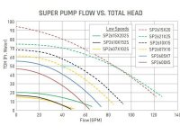
The pump is a Hayward 2610X15, and the flow curves are shown below but note that these flow curves are for a standard 1.5HP motor in a SP2610X15, and this one has an upgraded 2.2HP AO Smith motor so it should be more than sufficient by the numbers, I would think.
44080_0_2017822173343.jpg
Typically the booster pickoff is a 3/4 pipe so you do not divert 50% of the return water into the booster line.
I find this layout interesting because it appears to me that the output from the booster line goes from the standard 3/4 and is then fit into a 1.5-2" (I haven't measured this exact part, I'll do so today). The pickoff line does seem to be a 3/4 though. I could place this before the split as you say, and put a simple valve to keep it from diverting when not cleaning.
I can't see exactly how the booster pickoff connects into pipe 8 from your pics.
Close_Outlet.jpg
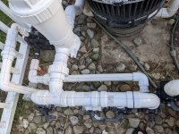
The pickoff you can see here, it is tapped into the return after the Jandy valve, so if the Jandy valve is closed, it creates suction in that return with no check valves in the system at all.
 
The filter cartridges were replaced last season, and cleaned every few months. I've fully cleaned them already for this season.
Sidebar: I just read here (and it makes sense) that cleaning a cartridge filter is the #1 cause of its wear (and replacement). Best to only clean it as needed. TFP recommends using the filter's pressure gauge to determine the actual need. Marty (@mknauss) is one of our experts:

You clean your filter cartridges when the filter pressure rises 25% above the clean pressure at the same pump rpm. Or once a year if your pressure never rises to the level of 25% above clean pressure.
 
  • Like
Reactions: pawsbrake
Allen, I thought I just read somewhere here that the suction manifold is not supposed to be higher than the pump's inlet (for priming reasons). Do you know anything about that?
That just makes priming a bit harder but as long as it isn't that much higher (<1') I don't think it would make much of a difference.
 
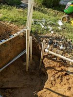
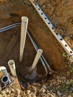
Just following up with some work I've done on this. It might not have been worth it to some, but I really wanted this done right. I moved the drain input so it was in front of the skimmers. Now I can tie the skimmers together and put a 3-way valve on it then the central drain tied in next. I was able to do this by routing the electrical away from the pipes and to the back.
 
  • Like
Reactions: Dirk
Sorry Dirk, I was trying to post with pictures but I was getting errors on my phone, anyways here are some progress photos. Feedback more than welcome :)
 

Attachments

  • 01.jpg
    01.jpg
    903.8 KB · Views: 7
  • 02.jpg
    02.jpg
    753 KB · Views: 7
  • 03.jpg
    03.jpg
    830.3 KB · Views: 7
  • 04.jpg
    04.jpg
    827.7 KB · Views: 7
Pipe Hard With a Vengeance! Way to go Karl!!

Only advice at this point: as you plan where each component is going to reconnect, try to picture how you would go about replacing it in the future, if you had to. Not just the main components, but down to every valve, PVC elbow, check valve, etc. If something broke, or cracked or leaked, and you had to cut it out, will you have enough PVC pipe between it and the component on either side to glue in a new one with PVC couplers between it and its neighbors.

You might not be able to leave enough PVC pipe between everything to make that possible, so be it. But where you can, leave the extra space. Otherwise, when things are too close together, you might have to start replacing more than one thing, including parts that are still working, just to be able to replace the one defective part. Or figure out how to "unglue" PVC joints. Which is not impossible, but not much fun.
 
  • Like
Reactions: pawsbrake
Thread Status
Hello , This thread has been inactive for over 60 days. New postings here are unlikely to be seen or responded to by other members. For better visibility, consider Starting A New Thread.