Re-Plumbing the Pool Equipment Pad

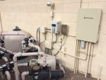
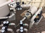
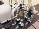
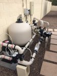
So, finally completed. Whew, that was quite the project all in all. I sure appreciate all of the help that I received from everyone. The photos above posted earlier in this thread, was the initial plumbing and electrical completion back in September , but I had yet to integrate the IntelliCenter automation, IntelliValves, IntellipH and a few other minor additions to the overall system.

Anyway, here is my completed "project" photos (don't hate me too much Jim, you were the one who gave me a some of these ideas :p )

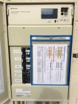
Load Center with IntelliCenter Install
IMG_4819.jpg


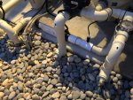
Plumbing and Electrical

IMG_4820.jpg

IMG_4823.jpg

IMG_4828.jpg

IMG_4827.jpg

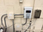
Low Voltage and Line Voltage Junction Boxes, Water Meter Enclosure and IntellipH Controller
IMG_4824.jpg


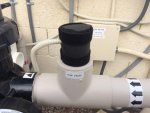
Temperature Probe wrapped in Foam Insulation
IMG_4825.jpg
 
Just reading your thread today. I am still green when it comes to a project like yours, but I must say it's clear you put a lot of thought into it, and it looks great. Congrats on tackling and completing a big job like that.
CM
Thanks very much. There were times that I thought that "I had bit off more than I could chew", but I got through it, with the help of others here.
I must say though, that I am a bit jealous that you are using a Dolphin Robot :p. Nice!
 
So, finally completed. Whew, that was quite the project all in all. I sure appreciate all of the help that I received from everyone. The photos above posted earlier in this thread, was the initial plumbing and electrical completion back in September , but I had yet to integrate the IntelliCenter automation, IntelliValves, IntellipH and a few other minor additions to the overall system.

Anyway, here is my completed "project" photos (don't hate me too much Jim, you were the one who gave me a some of these ideas :p )

Load Center with IntelliCenter Install

View attachment 90173

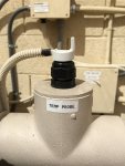
Temperature Probe wrapped in Foam Insulation

View attachment 90179
Can you explain what is happening with your temperature probe and how you installed it? Do you have a picture without the insulation? What did you jacket the wire with?
 
All
Can you explain what is happening with your temperature probe and how you installed it? Do you have a picture without the insulation? What did you jacket the wire with?
darinclifton
1. All of my wiring on my pad is protected with high temp split "wire loom". It's readily available at many outlets. Check out Amazon, Home Depot, Lowes, etc.
2. Here is a picture of my temperature sensor without the protective insulation. I used a standard 1/2" electrical strain relief compression fitting.
IMG_5635.JPG
 
All

darinclifton
1. All of my wiring on my pad is protected with high temp split "wire loom". It's readily available at many outlets. Check out Amazon, Home Depot, Lowes, etc.
2. Here is a picture of my temperature sensor without the protective insulation. I used a standard 1/2" electrical strain relief compression fitting.
View attachment 145812
Thanks so much for the reply, I see you have a ~2" T - what is the strain relief threaded into? I am surprised that you were able to get it to seal under pressure, how did you accomplish that task? I am assuming that you are getting good numbers. I am looking to do something better than the compression collar, they look like Rear. Your install looks very nice!
 
Last edited:
Thanks so much for the reply, I see you have a ~2" T - what is the strain relief threaded into? I am surprised that you were able to get it to seal under pressure, how did you accomplish that task? I am assuming that you are getting good numbers. I am looking to do something better than the compression collar, they look like Rear. Your install looks very nice!
I'm thinking this is brilliant. After looking again, it appears that you are using a spigot plug? I didn't realize that a strain relief plug could take pressure, a quick web search show ratings of 5 bar! please confirm that this was your approach and any difficulties that you might have run into . Thanks again for sharing your build!
 
darinclifton
Thanks so much for the reply, I see you have a ~2" T - what is the strain relief threaded into? I am surprised that you were able to get it to seal under pressure, how did you accomplish that task? I am assuming that you are getting good numbers. I am looking to do something better than the compression collar, they look like Rear. Your install looks very nice!
Correct 2"x2"x2" tee. 2" slip to 1/2" treaded adapter. Pretty sure it's a strain relief adapter but maybe it's called something else. I didn't think of the idea, I used info found here on TFP in other threads. You can try searching around on TFP for the proper name. Just not 100% sure now because it was a while ago.
I'm pretty sure that this is it.
I'm thinking this is brilliant. After looking again, it appears that you are using a spigot plug? I didn't realize that a strain relief plug could take pressure, a quick web search show ratings of 5 bar! please confirm that this was your approach and any difficulties that you might have run into . Thanks again for sharing your build!
Yea it's a good idea but I didn't think of it. I just followed guidance found here on TFP. No difficulties with this at all.
Thanks...
r.
 
I'm pretty sure that this is it. [Morris Products Nylon Cable Glands]
Had trouble with the Morris gland - acted like it was cross-threaded when close to tightening. Fortunately had some others, so used one of those. Even when tightened as much as I could, didn't seem like it would take much pressure to pop the probe. Currently have some velcro instead of a screw band to hold it in place. Did you need to add anything to prevent pop or were you able to get the gland tight enough? Afraid of tightening too much and damaging probe.
 

Enjoying this content?

Support TFP with a donation.

Give Support
I had originally thought a 2" x 3/4" x 2" tee was a cleaner install (I needed a hose bib for draining solar for winter), but a pool plumber corrected me, siting that was a good way to snap off my PVC if the bib got tripped on. So apparently 2" x 2" x 2" with a reducer is the better way.

I wrap all my wire and tubing stuff with the split loom, too, from Lowes. What does "high temp" mean? I think mine is "UV," but I figure I'll still need to replace it periodically. Better to replace that stuff than the much more expensive stuff I've got it protecting. Is there something tougher than the UV stuff I'm using?
 
  • Like
Reactions: MyAZPool
dianedebuda
I also agree with all points made by @Dirk above.

Much better to use 2"s x 2"s x 2"s tee's and then use either a 2"s x 1/2" Reducer Bushing Spigot x FPT (threaded) or a 2"s x 3/4" Reducer Bushing Spigot x FPT (threaded), depending on the application, for any acid injection, water temp, pH and/or FC sensors, IntelliChem Flow Cell Inlet/Outlet, etc., plumbing taps.

Like this.
2020-09-01_09-38-32.jpg
You will also find a very large selection (size and colors) of split loom on Amazon....

When using the morris glands, I've had no problems with leaking but I might have used just the right amount of teflon tape (not too much and not too little). 3-5 wraps should be about all you need. Take your time with the wraps (no dimples), and insure the tape is smoothed out and gets into all of the threads nicely with your finger before installing the male threads into the tap. Gently thread and don't over-tighten too much.
r.
 
Thanks @Dirk and @MyAZPool, but I'm not asking about the tee & reducer nor threading the gland into them. Have already done that. It's the smooth probe inserted into the gland and tightening that I'm having concerns about.
 
Oh, gotcha. Yea, I have not had any problems with that. Just keep working with it. Mine works fine. No leaks at all.
Maybe the one you got is defective somehow.
r.
 
Haven't tried it without the velcro strap, so maybe isn't a problem. Sure doesn't seem to take much to slide the probe out though. Just spooked I guess.
 
Haven't tried it without the velcro strap, so maybe isn't a problem. Sure doesn't seem to take much to slide the probe out though. Just spooked I guess.
You should be okay. Just work with it and take your time and it will be good. Like I said, over two years and zero problems with it coming loose, leaking or anything like that. (y)
 
What is the thought process on the 2x2x2 tee with bushing, vs a 2x2x1/2 tee? I understand for Dirk's situation where you are installing a hose bib which is metal and stronger than the surrounding materials, but for the temp probes and injection points, I would think that the 1/2" branch would be fine. Getting ready to FINALLY install my IntellipH and I will be adding several of these 'taps' so that I have locations for 'future' sensors, if necessary.

--Jeff
 
Well, if you're forcing me to fess up, I did the bibs correctly, but I didn't follow my own advice for the IpH probe, because it's all plastic so I figured that would snap before the tee did. Do as I say, not as I do!! ;) It was a moment of weakness! If I were to do it again, I'd use the 2x2x2.

intelliph 2.jpg
 
I think for the sensors and stuff like that, I prefer the ones with the 1/2" or 3/4" branch connections, as the temp probes might actually get into the flowing water instead of the weird quasi-stagnant pocket that is created from the larger 2" socket. But I'm weird like that. I definitely understand that from a strength perspective, the 2" branch will be able to withstand more side loading, especially with the bushing installed.

--Jeff
 

Enjoying this content?

Support TFP with a donation.

Give Support
Thread Status
Hello , This thread has been inactive for over 60 days. New postings here are unlikely to be seen or responded to by other members. For better visibility, consider Starting A New Thread.