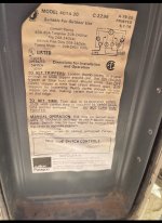
Thanks in advance for reading. Looking to replace pool timer - Currently Have Paragon 4004-71M mechanical timer (1997 and picked up a Dewenwils digital timer (2hp 120-277vac 40amp). Old timer is beat only allowing on/off.
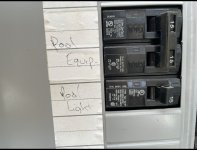
Set up from panel is 1x double pole 30amp breaker for “pool equipment” and 1x single pole 15amp breaker for “pool lights” (please see pics for detail - labels with a grain of salt - re-wired during solar install and may have been hastily labeled by tech ).
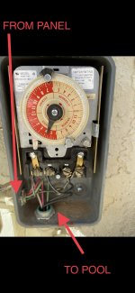
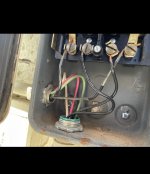
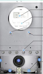
Current timer has 2x black wire in/out set up, I believe line & load
Bypassing the Timer are 1x white, 1x red, 1x green wire - entering box from left and leaving box at bottom along with 2 black connected wires.
wires from timer box feeding;
- deep end pool light,
- 3 receptacle tower containing from bottom up motor on/switch switch, pool light on/off switch, GFCI outlet
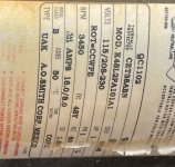
- Pool Motor - 1hp, 115/208-230 amps 16/8
QUESTIONS
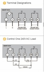
am I right in figuring this is currently wired for 1x 240v and should be wired for such in the new timer (diagram 4) and would someone be willing to provide more detail on the wire set up including in/out and going old to new
are the wires which bypass the current timer all feeding the light and GFCI? and with the new timer should they be installed or continue to bypass
Can post more pics if needed. Thanks!
Set up from panel is 1x double pole 30amp breaker for “pool equipment” and 1x single pole 15amp breaker for “pool lights” (please see pics for detail - labels with a grain of salt - re-wired during solar install and may have been hastily labeled by tech ).
Current timer has 2x black wire in/out set up, I believe line & load
Bypassing the Timer are 1x white, 1x red, 1x green wire - entering box from left and leaving box at bottom along with 2 black connected wires.
wires from timer box feeding;
- deep end pool light,
- 3 receptacle tower containing from bottom up motor on/switch switch, pool light on/off switch, GFCI outlet
- Pool Motor - 1hp, 115/208-230 amps 16/8
QUESTIONS
am I right in figuring this is currently wired for 1x 240v and should be wired for such in the new timer (diagram 4) and would someone be willing to provide more detail on the wire set up including in/out and going old to new
are the wires which bypass the current timer all feeding the light and GFCI? and with the new timer should they be installed or continue to bypass
Can post more pics if needed. Thanks!