Pentair Serial COM Port Expansion Board Installation

MyAZPool

Gold Supporter
Jul 3, 2018
2,294
Arizona
Pool Size
20500
Surface
Plaster
Chlorine
Salt Water Generator
SWG Type
Pentair Intellichlor IC-60
Background: Recently, I installed a Pentair Serial COM Port Expansion Board (Port Multiplexer), in my IntelliCenter Load Center. I thought I might share some information regarding this expansion board and its installation.
The Pentair Serial COM port expansion board can be used with any Pentair IntelliCenter, IntelliTouch and EasyTouch Automation Control System. A total of two (2) Serial COM Port Expansion Boards can be installed.
There are two reasons that a Pentair Automation user may wish to install this board.
1. An IntelliCenter user who may be interested in taking advantage of the full RS-485 capability of their IntelliValve(s) once the anticipated Pentair IntelliCenter over-the-air (OTA) update is released, that will allow for that functionality and/or,​
2. An IntelliCenter/IntelliTouch/EasyTouch user that wants more RS-485 /Serial COM port connectivity AND chooses not to "pigtail" those connections in the limited Serial COM port connectors located on the control system main boards (typically only two (2)).​

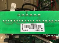
The part number for the Serial COM Port Expansion Kit is: 520818. The cost is approximately $60.00. I paid $57.90 on Amazon (no shipping or taxes).
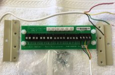
The following items are included in the kit:
1. One Serial COM Port Expansion Board populated with:​
- Three (3) four position screw terminal blocks (COM Ports) J1-J3​
- Four (4) two position screw terminal blocks (Serial Ports) J4-J7​
- Six (6) IntelliValve two pin connectors (these are for the yellow and green wires connected to the IntelliValve valve actuator). J8-J13.​
2. 12" long, four-conductor cable attached to two four-position terminal blocks (this wire connects one of the 4 pin screw connectors on the control system main board).​
3. Four-screws, two Expansion Board brackets and the Installation Guide.​
Any Pentair equipment/accessory that connects to four pin screw terminal blocks can be connected to the three four pin screw terminal blocks on the expansion board.​
NOTE: One COM port terminal block is used to connect to the control system main board.

The three COM Ports share a common bus. Thus, the following type equipment/accessories can connect to any of these ports. This list is just an example and not all inclusive.
Pentair Remote Controllers to include wireless controllers​
Indoor Remote Controllers​
i5x and i10x Expansion Load Centers​
ScreenLogic® Interface Protocol Adapter,​
IntelliChlor Chlorine Generator​
i-Link™ Protocol Interface adapter​
IntelliChem (NOTE: IntelliChem connections do not use the RED connection). Only the yellow, Green and Black)​
Spa-Side Remotes​

The two pin screw terminal blocks can be used for RS-485 or RS-232 communications for equipment such as:
Pentair IntelliFlo Pumps
Pentair UltraTemp and Hybrid Heat Pumps

INSTALLATION -
Note: The following is a detailed explanation of the installation (and any tips/tricks that I can think of) of the Serial COM Port Expansion Board in the Pentair IntelliCenter Load Center. Installing the expansion board in any other automation system may or may not be similar.

WARNING: ALWAYS remove power from the Load Center/Power Center and from any items that you are connecting before proceeding. De-energizing ALL applicable circuit breakers is the approved method of removing power from these items. Failure to do so may result in electrical shock and/or damage to equipment.

CAUTION: ALWAYS use approved anti-static precautions when handling circuit boards. Failure to do so may result in damage to equipment.


1. Remove the four adhesive backed supports using a 1/4" socket. (these are for use in older type load centers, that do not have the two applicable mounting screws for the expansion board).
2. Unlatch the front door spring latch to open the load center door.
3. Loosen the two access screws securing the IntelliCenter Control Panel using a 1/4" socket and fold it down.
4. Using a 1/4" socket, remove the two screws from the back of the load center upper low voltage compartment as illustrated below.
5. Install the two Expansion Board brackets and secure with the same two screws as illustrated below.
Note: Do not tighten yet. Leave these two screws slightly loose until after mounting the expansion board to the brackets.
2019-04-12_18-28-47.jpg
6. Mount the Expansion Board onto the bracket and secure with the four screws that are provided in the kit using a 1/4" socket as illustrated below. Then tighten the two screws that mount the brackets.

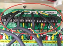
7. The Serial COM Port Expansion Board is shipped with the cable connectors plugged in to J2 and J3 of the expansion board. Remove the terminal connector J2 on the Expansion Board and connect it to a COM port on the IntelliCenter Control System Personality Board as depicted in the above illustrations.

8. If you have existing equipment and/or accessories (IntelliChlor, IntelliChem, IntelliFlo Pump, UltraTemp and Hybrid Heat Pumps, Remote Control Panels etc., connected to the IntelliCenter Automation System Mother Card remove the connector with attached wires and connect the connector to an available terminal on the Expansion board COM port (as shown above).

9. After the Expansion Board has been mounted and all equipment/accessories connected, close the control panel into its original position and secure it with the two access screws. Apply power to the system by energizing the applicable circuit breakers and close the load center front door. Fasten the spring latch.

Hope this helps with anyone installing the Pentair Serial COM Port Expansion Board in an IntelliCenter Load Center.
Please feel free to ping me if you have any questions...
r.
2019-05-13_10-34-15.jpg 2019-05-13_10-35-20.jpg
 
Last edited:
Myazpool...nice write up!

Can I ask what what functions you are planning to control (dynamically) with the intellivalve positioning ? I am wondering what advantages there will be over the standard 2-position actuators. Are you planning 3 (or more) positions for some valves? What kind of precision do you expect them to give...will it be like the “additional click” method of the standard actuator OR a finer adjustment with many more positions available ?

I am asking because I could see an application where a person might want to adjust a valve based on a psi reading, which I am considering.
jonpcar
Thanks...
Yes, I am planning on more than two valve positions for some of my valves. I plan on using the enhanced control (if you will) of some (if not all) of my Intellivalves, to more finely tune the positioning of the valves for various configurations using FEATURE CIRCUITS and then imbedding those FEATURE CIRCUITS within CIRCUIT GROUPS (macros). As you know, currently the intelliValve only has two positions available like any other valve actuator. But after the anticipated IntelliCenter update, it is rumored to then have five (5) preset positions, available to the user.

My understanding of this from talking with Pentair Tech Support and the local rep, is that once the IntelliValve has RS-485 communications with the IntelliCenter, the IntelliCenter logic will obtain position information from just where the valve diverter is located. Once I create different FEATURE CIRCUITS for different valve positions within a particular valve, then I can assign those FEATURE CIRCUITS (valve positions) to different CIRCUIT GROUPS (macros).

For example. right now, my spa intake valve (from my spa skimmer) has two positions. Position #2 is completely open or at 12.0 (180 degrees) (closing off intake of water from the pool and allowing full and normal use of the spa). The Home position is located at 21.0 (112.5 degrees). That position allows for a certain of amount of water to be suctioned from the spa and a certain amount from the pool. But when I change pump speeds for different cleaning cycles (schedules) or when I incorporate the suction side cleaner, I need different valve positions available, so I can more finely tune the water flow. Same with the spa make-up return line.

All of this is in part, due to the fact that I have an older type of pool/spa setup where the pool and the spa are at the same level (spa is not raised and does not have a "spillover" capability). Water level is equalized through a 6" equalizer line between the pool and the spa. If I don't get the valves positioned "just right" for both the Pool/Spa intake and the Pool/Spa return, my "spillover" will be on my kool decking :shock: or the inverse and my spa skimmer will be sucking air. That equalizer line can only handle so much water flow.

I also want the capability to more "finely tune" my water feature (3 sprays) valve. In the current mode. It's either ON or OFF. After the OTA, I can have several different positions for that valve depending on my "mood". ;)

As far as the precision of the valve position, that's predetermined by you. The IntelliValve has 48 available positions. Each "click" represents .5 or 3.75 degrees of movement between 0 and 180 degrees (or compass position of the valve diverter from 90 degrees to 270 degrees). My understanding is that you will make the determination on where each preset position (1-5) is located. Just as an example, lets say you set up your five positions like this:

Valve position #1 = IntelliValve position 0 (270 degrees) (Valve diverter closed to RH side or pipe, completely open to LH side or pipe)
Valve position #2 = IntelliValve position 6.5 (221.25 degrees)
Valve position #3 = IntelliValve position 13.5 (168.75 degrees)
Valve position #4 = IntelliValve position 20.0 (112.5 degrees)
Valve position #5 = IntelliValve position 24.0 (90 degrees) (Valve diverter open to RH side or pipe, completely closed to LH side or pipe)

Note: I kind of like using compass position, because in my mind, that tells me just where the diverter is located with reference to the valve housing (i.e. if the diverter is located right in the middle (equal water flow from both incoming pipes), that would be 180 degrees compass position (in a typical plumbing setup).

I don't know now (while reading this back to myself) if I helped or hurt :p, but I tried my best.
Thanks for the great questions...
r.
 
Last edited:
  • Like
Reactions: JaredF and jonpcar
AZpool, thanks for the explanation...I think you are going to be part of the elite 1% who fully understand this system and how to take advantage of it, haha. I hadn't looked at any documentation on the intellivalves, but I am impressed with 48 positions (3.75 degrees)...that's significantly finer resolution than actuators.

Only one thing I didn't understand in your comments was the " each 'click' represents .5 or 3.75 degrees" comment. What does the ".5" reference? Thanks again.
 
  • Like
Reactions: cousrey
jonpcar
AZpool, thanks for the explanation...I think you are going to be part of the elite 1% who fully understand this system and how to take advantage of it, haha. I hadn't looked at any documentation on the intellivalves, but I am impressed with 48 positions (3.75 degrees)...that's significantly finer resolution than actuators.
Well thanks. But the only thing "elite" about what I do now since retirement is "Goofing Off" (besides having to perform more "honey-do's", since I no longer have a valid excuse to get out of them. Hey, I bet we are not more than a couple of miles from one another. We need to get together one of these days and do some "pool checking out". I'm interested in your 3 DIY Waterfalls and buried Stenner Pump Tank. If you ever decide to make the "hyper-jump" to IntelliCenter, since I'm just down the road, I "work-for-food" :mrgreen:. Preferably Mexican! LOL....
Anyway, back to busi....

Only one thing I didn't understand in your comments was the " each 'click' represents .5 or 3.75 degrees" comment. What does the ".5" reference? Thanks again.
Each press (I call it a click) of either the Red Arrow or Yellow Arrow buttons, moves the diverter .5 In other words, if the diverter postion indicator (red light) is located at "0" and you press the Red Arrow button four times, the diverter position indicator will now be at "2". So each press represents .5 and moves the diverter within the valve housing 3.75 degrees.
Below is an excel spreadsheet that I put together that maybe explains this a bit better.
Notice that the bold numbers represent where you will see the red light on a single digit. Any of the positions between 2, 4, 6, 8 etc, both lights will illuminate. For instance, lets say that your valve diverter position is at 1.5. You will see both the 0 and the 2 lights illuminated.

I'd be happy to demo this to you in person sometime, but keep in mind, that I believe that you will require an IntelliCenter Automation System before you can take advantage of RS-485 communications with the IntelliValve. There may be other ways for the super-IT folks but that's above my "pay-grade".
Hope this helps a bit.

Please feel free to ping me at @MyAZPool, or PM me if you have any questions.
Take care.
r.
 
Last edited:
Wow, as always, you amaze me with your attention to detail. Thanks! Yes I know I wouldn’t be able to use the intellivalves YET in my system, but I am hoping that there will be those who decode the protocol and make the details available, haha. It might be awhile though, because to do that they will actually have to have the Intellicenter installed, thereby probably negating the need to decode the protocol. But there is a site that I will be keeping my eye on...

Intellivalves definitely have a role in the pool world. I think there are a small % of cases (and probably a much smaller % of users who can figure them out) where they really will be effective and/or necessary. However, being a gadget guy, I still think they are really neat and, for the incremental cost, I would definitely want them on all my valves on a new build!

I’ll PM you about the other stuff...thanks again!
 
So some dumb questions here. These are focused on DIY controllers. How would the RS-485 communication work? Right now it looks like the Intellivalve has a standard 3 pin connector that accepts a 24VAC to move it in one direction or the other. Is there another cable on the valves for communication?

I guess that since the valves require power to program them, you would need to constantly apply power to the valves from the relays in order to program them. Not a big deal but in my original design for standard actuators I can turn power off to the actuator after it reaches its desired position.

Anyway, I ordered an Intellivalve to mess around with, might be able to answer some of my own questions.
 
  • Like
Reactions: MyAZPool
So some dumb questions here. These are focused on DIY controllers. How would the RS-485 communication work? Right now it looks like the Intellivalve has a standard 3 pin connector that accepts a 24VAC to move it in one direction or the other. Is there another cable on the valves for communication?

I guess that since the valves require power to program them, you would need to constantly apply power to the valves from the relays in order to program them. Not a big deal but in my original design for standard actuators I can turn power off to the actuator after it reaches its desired position.

Anyway, I ordered an Intellivalve to mess around with, might be able to answer some of my own questions.
Hi Katodude...
So I connected one of my IntelliValves to the bus. I sent you some detailed info on PM..
r.
 
  • Like
Reactions: JaredF

Enjoying this content?

Support TFP with a donation.

Give Support
@MyAZPool - I know this is an old thread, but I'm looking to have an intellicenter further away from the equipment - equipment is at the rear of the yard, and we don't have a great location to mount the load center (and don't want to built a wall out there to mount it to).

There's 3 valves, a heater, and an intelliflo pump at the pad in the rear of the yard. If I add this expansion board in a box remotely by the equipment, I'd only need the 4 conductor from the Intellicenter to the expansion board, and then my heater, pump, and valves could all be 60' from the load center if I'm understanding this correctly.
The expansion card only has connectors on it for the (still unused) 2 pin rs485 conductors of the intellivalve, not the standard 3 pin valve connector.
 
@MyAZPool - I know this is an old thread, but I'm looking to have an intellicenter further away from the equipment - equipment is at the rear of the yard, and we don't have a great location to mount the load center (and don't want to built a wall out there to mount it to).

There's 3 valves, a heater, and an intelliflo pump at the pad in the rear of the yard. If I add this expansion board in a box remotely by the equipment, I'd only need the 4 conductor from the Intellicenter to the expansion board, and then my heater, pump, and valves could all be 60' from the load center if I'm understanding this correctly.
The Serial COM Port Expansion Board (Port Multiplexer) is only for RS-485.

2023-07-11_09-27-00.jpg

Yes, you could use it to remote any RS-485 connectivity for a short distance like 60'.
i.e. You could remote the RS-485 connections from your pump, IntelliChlor, heater and Intellivalves (which are not used yet).

However, as far as the power connections for your IntelliValves go (the white, red & black wires), you'll need 18-22 AWG 3-conductor wires for as many IntelliValves as you have and run those over to your load center for those particular connections.

Thanks..
r.
 
Last edited:
If you are already using both the RS485 ports (in my case: Heater + Pump) on the IntelliCenter. Do we need to add this expansion card in order to also hook up a Raspberry Pi via RS485? I've seen mention of "sharing" RS485 ports...but it wasn't clear to me if that was possible given that this expansion card exists. IE: Why buy this card if I can just add 2 devices to a single RS485 port....except for cases where you can't physically add more wires to a single port.
 
If you are already using both the RS485 ports (in my case: Heater + Pump) on the IntelliCenter. Do we need to add this expansion card in order to also hook up a Raspberry Pi via RS485? I've seen mention of "sharing" RS485 ports...but it wasn't clear to me if that was possible given that this expansion card exists. IE: Why buy this card if I can just add 2 devices to a single RS485 port....except for cases where you can't physically add more wires to a single port.
Like you said. Expansion card really only required when you can't physically double or triple up on the existing RS485 ports.
 

Enjoying this content?

Support TFP with a donation.

Give Support
Thread Status
Hello , This thread has been inactive for over 60 days. New postings here are unlikely to be seen or responded to by other members. For better visibility, consider Starting A New Thread.