Pentair 520657 Motherboard Comms Port Stopped Working

sedor121

Bronze Supporter
Feb 10, 2023
8
??
Hey everyone, I am new here but have been reading through some of the posts and it seems like this is a great forum for all things pool related! We have a Pentair Easy Touch 8 control system with a VS pump. Recently, the "Display Not Active" message on the VS intelliflo pump disappeared and the RPM's started showing. I also noticed that the Easy Touch system would not turn the VS pump on or off (all other features including the lights, secondary pump which is not a VS pump for water features etc still work just fine and the Easy Touch controller turns them on/off). I also noticed that my Screen Logic app stopped communicating. I went into the settings on the ET controller and the status under pump #1 says No Comm. I was hoping that maybe the cord had just gone bad so I bought a new cord and hooked it up but no luck.

So, I am now thinking that the comm port has gone bad which it seems like this is a common problem just from quickly reading through some other posts. Here are my questions:

1. Is there a way to make 100% sure it is the Comm Port and not another issue?

2. Based on my troubleshooting so far, could this issue be related to anything else?

3. Assuming it is the Comm Port, is that something that can be replaced or bypassed? If not, do I need to replace the motherboard?

4. If I do need to replace the motherboard is there a way to backup all of the settings prior to doing so? The pool installer who installed everything no longer lives here and I wouldn't know the first thing about trying to re-program everything.

Thank you SO much in advance for any info you might be able to share!!

Scott
 
Welcome to TFP.

It is more likely your Screenlogic box went bad. When a device RS-485 fails it loads down the COMM bus and everything stops working.

Disconnect the Screenlogic wire at the ET and have only the pump RS-485 wire connected. See if DISPLAY NOT ACTIVE comes back on the pump when the ET is in AUTO mode.

Or disconnect the pump and just and Screenlogic connected and see if it works.

Also check both wires carefully for any breaks in the insulation.

Be sure to power down everything before you touch any wires.

Report back what you find.

@Jimrahbe
 
Thank you SO much for the response Jim! I neglected to mention in my first post that we also had the spa side remote connected to the comms port. So, in total we had three things connected to the port - the spa side remote, the VS pump and the screenlogic2 system. I removed everything and reconnected the VS pump then restarted everything. The intelliflo screen immediately went to the Display Not Active screen and everything worked. I then reconnected the screenlogic2 system and the ET controller still worked and the intelliflo screen still said Display Not Active. This leads me to believe the issue was the spa side remote which had actually stopped working a few weeks ago. However, now when I log into the screenlogic2 app there is no data and nothing works (no air temp, pool temp etc). I tried to restart the system inside that is connected to our router and I noticed that when it powers up the green power light is blinking pretty fast and the RF/TX lights are off (usually they flash in an amber color which means they are communicating with the antennae outside). I tried restarting it numerous times but same issue. I double checked that I got all of the cords reconnected firmly and in the proper slots (red, green, yellow, black). Any ideas on what might be happening? Again, thank you for all the help and at least for now I can manually start the system from the ET controller.
 
Glad you figured out your spa controller was causing the problem.

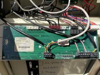
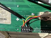
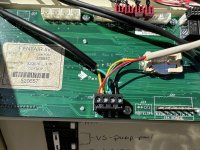
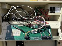
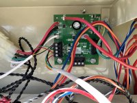
Post pics of your EasyTouch board showing the comm port connections and your Screenlogic boxes Outdoors and indoors.

Did you make any changes to your router or home network?
 
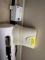
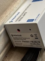
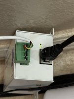
Thanks again for the follow up. I have not changed anything with the router or home network. Attached are photos of the boxes inside and the comm port and overall setup. I forgot to take a photo of the outdoor antenna so I will have to go do that but essentially it is just attached to the wall. Question - my assumption was that the third connection was the spa side remote but could it have been the antenna for the screen logic system? Does the screen logic system have two connections to the comm port - one for the board (shown in picture below) and one for the antenna? Just wondering if what I thought was the spa side remote cord could have actually been the antenna cord in which case that would mean that the antenna is what is causing the system to stop working. Appreciate your thoughts and any info you might be able to share.
 

Attachments

  • IMG_2758.jpg
    IMG_2758.jpg
    362.7 KB · Views: 7
  • IMG_2759.jpg
    IMG_2759.jpg
    282.3 KB · Views: 6
  • IMG_2760.jpg
    IMG_2760.jpg
    285.2 KB · Views: 6
  • IMG_2761.jpg
    IMG_2761.jpg
    572.9 KB · Views: 8
  • IMG_2762.jpg
    IMG_2762.jpg
    569.7 KB · Views: 8
  • IMG_2763.jpg
    IMG_2763.jpg
    594.2 KB · Views: 8
  • IMG_2764.jpg
    IMG_2764.jpg
    461 KB · Views: 8
  • IMG_2765.jpg
    IMG_2765.jpg
    486.5 KB · Views: 7
Your spa side remote the 4 button or 10 button?

You have an IntelliChlor SWG?

I see two wires connected to the main board J20. I am assuming the black cable goes to your pump and the white cable connects to the IntelliChlor surge board. Then on the IntelliChlor surge board Img_2765 the white wire connects with another white wire leading to the IntelliChlor.

So I don’t see a wire connecting your ScreenLogic.

You need to follow the wires and see what devices are at the other end.
 
ok I think we are getting somewhere! The black wire that is connected to the comm port is the VS pump and the white cord that is connected to the comm port goes to the intellichlor surge board. The white cord coming off of the intellichlor surge board goes to the spa side remote which is a 10 button remote. The white cord that I did not hook back up which I originally thought went to the spa side remote actually goes to the screenlogic2 transceiver/antenna. Without that cord hooked up everything runs fine and when I connect that cord that's when I have the communication issue with the VS pump. So, is it safe to say the culprit is the screenlogic2 transceiver/antenna?

If so, could it just be the cord or do you think it's the actual transceiver (I inspected the entire cord and there is no visible damage to it)? If it is the transceiver, is it possible to just buy the transceiver or do you recommend getting a whole new setup kit? Again, thanks for all the help!
 
The surge board that Allen pointed out acts like a "port expander" which basically means it has 3 ports on it (one goes back to J20 on the outdoor board). This isn't your problem, but I would rewire it so that each comm cable is by itself on a black terminal block... it's just cleaner and makes troubleshooting easier (if you weren't aware, the terminal blocks pull off the board).

So if you've checked the wire going from the surge board to the screenlogic transceiver and it's ok, I'm inclined to agree with Jim that the card is dead. Look at the LEDs on the card and see if there is any activity on TX/RX (the outdoor card is the same as the indoor card, but without a dc power jack). The wireless link is sold as a set... there's a ton of single cards on eBay but you cannot buy just one transceiver because they're matched to each other via the code that's written on them (and you can't reset the code).

If you have the ability to do so, power up the card with 12 volts dc and check the current draw... it shouldn't be more than 30mA. If it is, the comm chip is likely fried... it's an 8-pin chip labelled U700 on the back of the tranceiver card.

One last thing, you can move the screenlogic outside (permanently or as a test), and connect IT to one of the comm ports on the surge card, and then use a cable or a wireless ethernet bridge to connect it to your home network (I wouldn't run a permanent ethernet cable because those also seem to attract lightning)
 

Enjoying this content?

Support TFP with a donation.

Give Support
The surge board that Allen pointed out acts like a "port expander" which basically means it has 3 ports on it (one goes back to J20 on the outdoor board). This isn't your problem, but I would rewire it so that each comm cable is by itself on a black terminal block... it's just cleaner and makes troubleshooting easier (if you weren't aware, the terminal blocks pull off the board).

So if you've checked the wire going from the surge board to the screenlogic transceiver and it's ok, I'm inclined to agree with Jim that the card is dead. Look at the LEDs on the card and see if there is any activity on TX/RX (the outdoor card is the same as the indoor card, but without a dc power jack). The wireless link is sold as a set... there's a ton of single cards on eBay but you cannot buy just one transceiver because they're matched to each other via the code that's written on them (and you can't reset the code).

If you have the ability to do so, power up the card with 12 volts dc and check the current draw... it shouldn't be more than 30mA. If it is, the comm chip is likely fried... it's an 8-pin chip labelled U700 on the back of the tranceiver card.

One last thing, you can move the screenlogic outside (permanently or as a test), and connect IT to one of the comm ports on the surge card, and then use a cable or a wireless ethernet bridge to connect it to your home network (I wouldn't run a permanent ethernet cable because those also seem to attract lightning)
Thanks for all the info and hope everyone enjoyed their Super Bowl weekend! I am going to try all of these suggestions and I will report back with what I find. Quick question, when you say the black terminal blocks pull off the board are you saying that the entire black module can just be pulled straight off the board and then plugged right back in? If so, that would make it so much easier to wire them as I could pull the black module off, wire it and then simply plug it back into the board. I just wanted to double check that is accurate before I try to pull something off of the mother board haha. Thanks!
 
Thanks for all the info and hope everyone enjoyed their Super Bowl weekend! I am going to try all of these suggestions and I will report back with what I find. Quick question, when you say the black terminal blocks pull off the board are you saying that the entire black module can just be pulled straight off the board and then plugged right back in? If so, that would make it so much easier to wire them as I could pull the black module off, wire it and then simply plug it back into the board. I just wanted to double check that is accurate before I try to pull something off of the mother board haha. Thanks!
That is correct. The black connector slides onto four pins that are sticking up from the board.

Power down the panel before touching any connectors or wiring.
 
  • Like
Reactions: ogdento
Hi Everyone - here's an update: system has been running fine without the screenlogic2 system connected only bummer is the spa side remote also went out so the only way to get the spa to work is to go over to the ET controller and manually turn it on. This is fine for now but definitely want to get things back up and running normally.

So, I reconnected the screenlogic2 transceiver to the comm port on the intellichlor surge board and then restarted the system. The system goes right back to No Comm on the status and the VS lcd screen no longer says Display Not Active. So, we know it is something with the screen logic transceiver. While I had the system up and running I took a look at the outdoor transceiver card and the green light is on and solid but no activity on the Tx/RX light (the small amber light next to the green light). The next step was that I replaced the cord to see if that was the problem and no luck - same issue.

At this point, is it pretty safe to say that the outdoor transceiver board is fried and if so is the only option to replace the whole screenlogic2 system?

If I were to permanently move the indoor system outside and get a wireless ethernet bridge would I essentially just move that whole system outside including the DC adapter? Trying to figure out if that is possibility as I would need to somehow keep it out of the elements. The ethernet bridge is about $45 whereas a whole new system is almost $700 so just trying to see if that might be an option.

Again, thank you for everyone's help here - it is really appreciated :)

PS: I wasn't able to test the draw as I didn't have the proper tools
 
Having an air gap with a wireless connection between your outdoor panel and your indoor network protects your network from lightning blowing out a lot of indoor equipment.

Hardwiring your outdoor panel to your indoor network puts other equipment at risk.
 
I do! Here is the thread I followed -- Add WiFi to Pentair Protocol adapter for peanuts.

It somewhat violates the putting of low voltage item in the high voltage cabinet, so be aware of that.
I used a pigtail off my convenience outlet with a female plug to plug in the wifi extender. It hangs under the cabinet. My climate is very dry so I have no issue with it. So consider that if you have different conditions.

The connection works great. I have a TP link router and TP link extender. They mesh automatically.
 
Thanks for all the info! So, right after I posted that I got to thinking that maybe I had the wrong cord - I live in Maui and it is difficult to find things here. I went to Ace Hardware and asked for the same cord and the lady told me it was the same cord. Looks similar but had some different markings. So, just to be absolute certain it wasn't the cord I pulled the excess spa side remote cord out from the ET controller since I am no longer using the spa side remote and then I used that cord to re-wire the screenlogic2 transceiver. I knew that the two cords were the same and I knew the spa side remote cable was good (or at least it was a week or two ago). I fired the system up and everything works perfectly! In the end, it was the cord going from the comm port on the ET motherboard to the screenlogic2 transceiver.

While I was in there I went ahead and rewired the other comm ports to make everything easier to troubleshoot next time - I had no idea the intellichlor surge board had the extra comm ports or that you could pull those off to quickly/easily rewire everything - saved me a ton of time! I would love to donate to this forum so just let me know how - you just saved me about $700 on a new screenlogic2 system!
 
Glad it turned out to be the wire. It often is the problem.

 
Thread Status
Hello , This thread has been inactive for over 60 days. New postings here are unlikely to be seen or responded to by other members. For better visibility, consider Starting A New Thread.