New Build - Austin, Texas - Slide Video

The trees that were in the way of the dig have been removed and the pool outline has been painted. Now we are waiting on an inspection before we can dig.

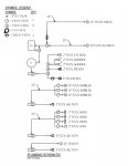
I have an IntelliCenter question for the experts. I am getting the IntelliCenter i10PS, so my understanding is that this has 10 relays. What I'm not completely sure of is what all takes up a relay. I have attached a copy of the plumbing schematic for reference. Here is a list of everything I can think of that I would like to control independently/automatically:
  1. Intelliflo Pump 1 - Main filter pump
  2. Intelliflo Pump 2 - Spa pump
  3. Intelliflo Pump 3 - Water sheers and water slide pump
  4. Intelliflo Pump 4 - Additional spa pump and Globrite bubbler pump
  5. IntelliChlor IC60 and IntelliPH - My understanding is that these are connected in series, so should only use one relay
  6. Heater
  7. Spa Blower
  8. Main Pool Lights
  9. Pool Tanning Deck Lights
  10. Spa Lights
  11. Globrite Bubbler Lights
  12. Deck Step Lights
  13. Water Sheers
  14. Water Slide
  15. Globrite Bubblers
  16. Chiller (if needed in the future)
So with this list I am obviously over 10 items. Now I think that IntelliValves don't use up a relay. Is that correct?

Assuming that is correct, then I can get independent control of the water sheers versus the water slide via a IntelliValve setup in a 3-way configuration for pump 3. I would also be able to get an independent control of the GloBrite bubblers and extra spa support via another IntelliValve setup in a 3-way configuration for pump 4. So I think that would take care of items 13-15 without using a relay.

From reading this great guide (IntelliCenter Quick Reference Information Guide), I am under the impression that a heater uses a separate type of connection that does not eat up a relay. Is that correct?

If my assumptions above are correct, then I think that would leave me with 11 items to use a relay (taking away items 6 and 13-15 from the list above). 10 relays is the maximum, correct? There isn't an expansion card available for more relays?

Hopefully there is something I am incorrect on, but otherwise I think that means I need to either combine my Main Pool Lights and Pool Tanning Deck Lights (items 8 and 9) into 1 zone, or don't put my Deck Step Lights (item 12) into the IntelliCenter and control those separately somehow.

This all ignores if I want to add a chiller at a later point in time. A chiller would eat up a relay if I decided to get one of those, correct?
 

Attachments

  • 2020-07-27 15.48.25 - 50 Pct.jpg
    2020-07-27 15.48.25 - 50 Pct.jpg
    853.1 KB · Views: 65
  • 2020-07-27 15.48.22 - 50 Pct.jpg
    2020-07-27 15.48.22 - 50 Pct.jpg
    777.5 KB · Views: 92
  • Plumbing Schematic.jpg
    Plumbing Schematic.jpg
    41.4 KB · Views: 91
  • Like
Reactions: vermaraj
22,

  1. Intelliflo Pump 1 - IntelliFlo pumps do not use a relay. But need to see if the IntelliCenter can control more than 2 IntelliFlos.. ??
  2. Intelliflo Pump 2 -
  3. Intelliflo Pump 3 -
  4. Intelliflo Pump 4 -
  5. IntelliChlor IC60 and IntelliPH - My understanding is that these are connected in series, so should only use one relay - The IC60 must be powered by the pump/filter relay. I personally would not use the IntellPH, just because it controls the SWCG... Talk with @MyAZPool ...
  6. Heater - Does not require a relay
  7. Spa Blower - Needs a relay
  8. Main Pool Lights. Each light that you want to independently control needs a relay and a low voltage transformer.. (Transformer depends on the type of light and fixture)
  9. Pool Tanning Deck Lights -
  10. Spa Lights -
  11. Globrite Bubbler Lights
  12. Deck Step Lights
  13. Water Sheers -Does not need a relay
  14. Water Slide - Does not need a relay
  15. Globrite Bubblers
  16. Chiller (if needed in the future) Unknown, I would save a relay just in case.
The 3 position valve driver does not yet exist.. I would not plumb it so that you have to use something that "may" never exist.

Thanks,

Jim R.

Thanks Jim. Regarding the 3 position IntelliValve, the IntelliValve user guide has an example of how to use it with a three way setup (1 inflow, 2 outflows). Are you saying it can't actually do this currently?
 
IntelliFlo pumps do not use a relay. But need to see if the IntelliCenter can control more than 2 IntelliFlos.. ??

According to the IntelliCenter installation guide:
  • Supports up to 16 IntelliFlo VF and VS Pumps
  • IntelliChem Controller: Supports one per body
  • IntelliChlor Salt Chlorine Generator: Supports one per body
 
Thanks Jim. Regarding the 3 position IntelliValve, the IntelliValve user guide has an example of how to use it with a three way setup (1 inflow, 2 outflows). Are you saying it can't actually do this currently?

22,

At this point all automated valves only have two positions... The actuator drives from point A to B or B to A, but cannot drive from A to B and then C..

So with a three way set up you can have all the inflow going out port A or port B but the valve cannot stop so that the inflow goes out port A and B... You can manually set the valve to do anything in between, but electrically the valve moves all the way from one stop to the other.. You can set the stops to different places, but it will always move from one stop to the other.. In theory, Pentair is working on a system to use the IntelliValve to move and stop at whatever location you want, but that has yet to be released.

I looked at your drawing and can't tell which of those valves you want to automate???

Also.. You want to be able to manually adjust the input of the two skimmers.. This is because the far skimmer will need more suction than the near skimmer.. If they are connected together, as in your drawing, you won't be able to adjust them..

Thanks,

Jim R.
Got it! That makes sense.

Agreed, the plumbing schematic is going to need revision.

Thanks for the comment about the skimmers, I did not know about that!
 
Thanks for the comments everyone. With your comments and the write ups from @MyAZPool, I have mapped out how I think all of my equipment will connect to my IntelliCenter i10PS. Note that due to the number of RS-485 connections, I think I will need to add a Serial Com Expansion Board. I still have to map out exactly how many IntelliValves I think I will need, but I think I will likely also need an IntelliCenter Valve Expansion Board. I'll figure out the IntelliValves later. Does the following table of equipment and connections look accurate?

ItemEquipmentConnectionPower
1Intelliflo Pump 1 - Main Filter PumpRS-485240V
2Intelliflo Pump 2 - Spa PumpRS-485240V
3Intelliflo Pump 3 - Water Sheers and Water Slide PumpRS-485240V
4Intelliflo Pump 4 - Bubblers and Additional Spa PumpRS-485240V
5HeaterHeaterCan be either 120V or 240V?
6ChillerAux Relay240V
7IntelliChlor IC60 and IntelliPHRS-485Low Voltage through Intellicenter?
8Spa BlowerAux Relay120V
9Pool LightsAux RelayLow Voltage
10Pool Shelf LightsAux RelayLow Voltage
11Spa LightsAux RelayLow Voltage
12Bubbler LightsAux RelayLow Voltage
13Landscape LightingAux RelayLow Voltage

Based on the above table, I am coming up with 5 items that use a RS-485 connection, 7 items that use Aux Relays, and the heater uses its own special connection on the main motherboard.

The part that I am a little questioning myself on is related to the IntelliChlor/IntelliPH connection. The IntelliCenter Installation Guide shows the IntelliChlor connecting to a special connection on the load center for power and connecting to a RS-485 for data. I have seen other posts on the forum mention connecting it to the Pump/Filter relay, but since the IntelliFlo pumps don't use the Pump/Filter relay, I am a little lost on what that means.
 
Sparks22

You probably will not be able to control your chiller power via an Aux Power Relay. The max amperage rating for those relays are 25 amps I believe. Pretty sure that any chiller would be well over that. Controlling chillers currently via the RS-485 bus has been a big contention and has been hit and miss, depending on the model of chiller or heat pump. There are several threads on TFP with in-depth discussions regarding this matter.

Everything looks good in my opinion. However, here is one thing that I don't know. Have you checked to see if you can control (On/Off and Speed Control), more than one IntelliFlo via the RS-485 bus and not control its power via a power relay. I don't see why not, but I'm just not really sure about that at this point.

Maybe someone who has more than one IntelliFlo connected to the bus can offer up some insight here.

Have you mapped out your Circuit Breakers? You got a lot of equipment there and those four pumps are going to take up 8 circuit breaker slots alone (4x double-pole breakers), if you plan on putting each pump on it's own breaker. That only leaves you with one double-pole or two single-pole breakers. I looked through your thread and I didn't see any mention of an aux panel or how you plan on powering all of this equipment.

Things to think about. ;)

Thanks...
R...

EDIT. Oh yea, regarding your question at the end of your post. You can wire the filter pump directly to a breaker or to the "LINE" side of the filter pump relay (NOT the "LOAD" side). Whatever works for you. Just as long as the pump is wired to continuous power. The IntelliChlor transformer is wired to the "LOAD" side of the Filter Pump relay. This prevents the IntelliChlor from being energized without the Filter Pump circuit (and the filter pump) being on also.

The IntelliChlor Controller Circuit Board is wired to the RS-485 bus. See IntelliChlor Controller Circuit Board
 
Last edited:
4 Intelliflo pumps seems like too much.

1 for the pool and features and one for the spa jets should be sufficient.

I'd say 4 pumps is too many also, but it depends upon application. Have you considered the noise factor when you have all those going (and the spa blower)?

I think you could have one pump for both the pool and spa and ramp up rpm for the latter when in use (you'd need valves and actuators for intake/returns).

Then you could have another for the water slide and features, again each individually controlled by valves/actuators. I'm not an expert, but I think it's feasible.
 

Enjoying this content?

Support TFP with a donation.

Give Support
I'd say 4 pumps is too many also, but it depends upon application. Have you considered the noise factor when you have all those going (and the spa blower)?

I think you could have one pump for both the pool and spa and ramp up rpm for the latter when in use (you'd need valves and actuators for intake/returns).

Then you could have another for the water slide and features, again each individually controlled by valves/actuators. I'm not an expert, but I think it's feasible.

Agreed the 4 pumps feels high. They ran it by the Pentair rep who looked at all of the features and came up with the suggestion of 4. One consideration is that the spa has 14 jets in it (2 seats with 5 each, and 4 single jets), so they were worried about 1 pump feeding the spa not being able to push enough water to that many jets.

So it ends up with 1 pump for the filter and heater loop, 1 pump to drive the water sheers and water slide, 1 pump dedicated to the spa jets, and 1 pump that does the bubblers and will supplement the spa jets. The plumbing schematic needs a little work, but that is what the intent was.

I ended up coming to terms with having the 4 pumps because for the large cost of the project, I didn't want to pinch pennies and potentially not be satisfied with the results. I think that having the 4 pumps actually will end up quieter than if I were to try to do it with 2 or 3 pumps since the 4 pumps would be able to run at lower RPMs than if I only had 2 or 3 pumps?
 
I would use 3". The intelliflow at 180gpm exceeds the maximum flow of 10ft/sec in a 2 1/2" suction line. May not be a problem, but it isn't a big cost either.

So they ended up with 3" for the drains and suction lines that pass the water to the pump. The pipes leaving the pump are set as 2 1/2", but get split further into smaller pipes as they approach the returns/features. Does that sound good? Or should they be using 3" after the pump up until they split off to the individual returns/features?
 
Sparks22

You probably will not be able to control your chiller power via an Aux Power Relay. The max amperage rating for those relays are 25 amps I believe. Pretty sure that any chiller would be well over that. Controlling chillers currently via the RS-485 bus has been a big contention and has been hit and miss, depending on the model of chiller or heat pump. There are several threads on TFP with in-depth discussions regarding this matter.

Everything looks good in my opinion. However, here is one thing that I don't know. Have you checked to see if you can control (On/Off and Speed Control), more than one IntelliFlo via the RS-485 bus and not control its power via a power relay. I don't see why not, but I'm just not really sure about that at this point.

Maybe someone who has more than one IntelliFlo connected to the bus can offer up some insight here.

Have you mapped out your Circuit Breakers? You got a lot of equipment there and those four pumps are going to take up 8 circuit breaker slots alone (4x double-pole breakers), if you plan on putting each pump on it's own breaker. That only leaves you with one double-pole or two single-pole breakers. I looked through your thread and I didn't see any mention of an aux panel or how you plan on powering all of this equipment.

Things to think about. ;)

Thanks...
R...

EDIT. Oh yea, regarding your question at the end of your post. You can wire the filter pump directly to a breaker or to the "LINE" side of the filter pump relay (NOT the "LOAD" side). Whatever works for you. Just as long as the pump is wired to continuous power. The IntelliChlor transformer is wired to the "LOAD" side of the Filter Pump relay. This prevents the IntelliChlor from being energized without the Filter Pump circuit (and the filter pump) being on also.

The IntelliChlor Controller Circuit Board is wired to the RS-485 bus. See IntelliChlor Controller Circuit Board

Thanks for the review!

Noted on the chiller, I will do some more research there.

Interesting question about the ability to control more than one IntelliFlo and remain all the capabilities. I tried to do some research and came across this in the instruction manual for the IntelliTouch system. It basically says that for that system, it can control up to 8 IntelliFlo pumps and individually address them through the RS-485 data connection, which allows for unique programming of the units. I didn't see similar wording in the IntelliCenter instruction manual, but hopefully since that is a newer system than the IntelliTouch they wouldn't have lost that same ability.

2020-07-29 21.13.28.jpg

For the power, I think that you are correct that I am hitting up against the limits of a single load center. I was starting to try to get at that with the Power column in my table. Assuming it won't all fit on one, then I think the easiest thing would be to add a second load center?

I have a further question about putting one of the IntelliFlo pumps onto the filter pump relay. If I put 1 of the IntelliFlo pumps on the filter pump relay, that relay actually provides the power to the IntelliFlo pump? So then that would free up 2 breaker spots in the load center? Or am I thinking about this incorrectly and each IntelliFlo pump will require 2 breaker spots in the load center no matter what?
 
  • Like
Reactions: MyAZPool
Sparks...
My assumption would be, that if that is the case with the IntelliTouch, then the same should hold true with the IntelliCenter as well. Just another case of lack of info within the documentation. I would just try to get a confirmation from tech support on that, but I'm pretty sure its the same.

Okay, you really should have a separate breaker for each IntelliFlo in my opinion. I highly recommend the following.

NO1596206403872.pngTE: It is recommended that when using any Pentair IntelliFlo Pumps in conjunction with an IntelliCenter installation, the Pentair PA220GF GFCI double-pole circuit breaker(s) should be utilized instead of the similar Siemens QF220 GFCI breaker. The Pentair PFG (PA220GF) breakers are noted to possess a higher quality control and are designed to help prevent the GFCI circuit breakers from falsely tripping due to IntelliFlo pump harmonics (courtesy: @Jimrahbe). See this TFP post for additional information.


You're getting things a bit confused regarding the wiring of pumps to relays..

If you want to connect the filter pump power conductors to the LINE side of the Filter Pump Relay, that's fine. It has the same effect as connecting it directly to the breaker. Just DON'T connect it to the "LOAD" side of that relay. That would be incorrect. The "LINE" side of the power relays are connected directly to the breakers. Lights, Spa Blowers, "single speed" pumps, etc are connected to the "LOAD" side of the relays. BUT with the exception of equipment that are controlled via an RS-485 control cable, such as IntelliFlo Pumps.

IntelliFlo pumps (especially the Filter Pump), should be wired "HOT" at all times if you want to control them via RS-485 (which is the correct method).

Thanks...
r.
 
Sparks...
My assumption would be, that if that is the case with the IntelliTouch, then the same should hold true with the IntelliCenter as well. Just another case of lack of info within the documentation. I would just try to get a confirmation from tech support on that, but I'm pretty sure its the same.

Okay, you really should have a separate breaker for each IntelliFlo in my opinion. I highly recommend the following.

NOView attachment 156004TE: It is recommended that when using any Pentair IntelliFlo Pumps in conjunction with an IntelliCenter installation, the Pentair PA220GF GFCI double-pole circuit breaker(s) should be utilized instead of the similar Siemens QF220 GFCI breaker. The Pentair PFG (PA220GF) breakers are noted to possess a higher quality control and are designed to help prevent the GFCI circuit breakers from falsely tripping due to IntelliFlo pump harmonics (courtesy: @Jimrahbe). See this TFP post for additional information.


You're getting things a bit confused regarding the wiring of pumps to relays..

If you want to connect the filter pump power conductors to the LINE side of the Filter Pump Relay, that's fine. It has the same effect as connecting it directly to the breaker. Just DON'T connect it to the "LOAD" side of that relay. That would be incorrect. The "LINE" side of the power relays are connected directly to the breakers. Lights, Spa Blowers, "single speed" pumps, etc are connected to the "LOAD" side of the relays. BUT with the exception of equipment that are controlled via an RS-485 control cable, such as IntelliFlo Pumps.

IntelliFlo pumps (especially the Filter Pump), should be wired "HOT" at all times if you want to control them via RS-485 (which is the correct method).

Thanks...
r.

MyAZPool,

Thanks for this post, I think that you finally made it click in my head about the relationship of the breakers and the relays. Each relay needs to be connected to a breaker in order to provide power to the relay. So even though I can save relays by just connecting the IntelliFlo pumps directly to the breakers, that doesn't help me on how many breakers I am using.

I think that I am most of the way there. The last thing I am not sure about is hooking up the IntelliChlor IC60. I think I understand that the point of hooking the IntelliChlor up to the Filter Pump relay is that it will only give the IntelliChlor power if that relay is energized, which means the pump that is also connected to that relay must also be energized. But with the IntelliFlo essentially always being energized but only being turned off if the data cable tells it to turn on, I feel like that still gives the chance that the IntelliChlor could get turned on by the Filter Pump relay but the data cable fails to tell the IntelliFlo pump to turn on? Or is there another piece of logic that I am missing there?
 
22,

There is a very small chance of that the cell will get power but the pump will not be running.. The system should not allow it, but if it did, you still have the secondary or backup safety device, the flow switch.. The system works very well for the thousands and thousands of units out there now.. It is something that I would not worry about.

Thanks,

Jim R.
Hi Jim,

Thanks for the note, definitely not intending to be a worry wart of that issue, just have ready a lot of warnings on this forum about making sure to not power on the IntelliChlor without the pump running. Is the flow switch that you mention built into the IntelliChlor, or is that a separate item that I would have installed?

Thanks!
 
Sparks,
Just reiterating what Jim said. If you wire the IntelliChlor transformer to the "LOAD" side of the Filter Pump Power Relay (which is the correct method), there is little to no chance that the pump will not be running while the IntelliChlor transformer is energized. The only chance that I can imagine where that could occur, is if the pump motor fails or seizes for some reason. And that is what the flow sensor that is built into the cell is designed for (redundancy).

If the flow sensor fails at the same time the pump fails, then it either just "wasn't your day" or you have really irritated the swimming pool gods in some way. :p

You "can" have MORE control over when the IntelliChlor is actually powered by incorporating an advanced "non-standard" method of wiring the IntelliChlor transformer, that I refer to as a "jumpered" relay. Myself and a few others use this method for additional control over the IntelliChlor and in some cases heaters as well. By utilizing this method, the IntelliChlor transformer is only energized when it's own relay is energized through the use of an AUX circuit. The pump circuit must still be on, since this additional relay obtains its power from the "LOAD" side of the Filter Pump relay. Then the IntelliChlor is only "ON" when that AUX Circuit is on. For additional information regarding this "non-standard" installation method, see the following post....

One caveat. You will need one spare power relay in order to incorporate this method if you choose to do so.
Thanks...
r.
 
We got the forms about half put up on Saturday. Seems like a weird place to stop. Trying to get on the schedule for the excavator but they can't seem to pin down a date.

2020-08-01 15.02.23.jpg
2020-08-01 19.56.55.jpg
 

Enjoying this content?

Support TFP with a donation.

Give Support
Thread Status
Hello , This thread has been inactive for over 60 days. New postings here are unlikely to be seen or responded to by other members. For better visibility, consider Starting A New Thread.