My NEW Pool Automation Controller

That is a very impressive GUI on the phone app... is it skinnable :p... if so I want the LCARS theme? Sorry its the geek in me.
Considering I barely know what a skin is...haha...no. I looked at that LCARS site and can't even figure out what it is for...something to do with StarTrek, but definitely not the StarTrek I remember (1967-69)...:rolleyes:

Still looking forward to checking out those waterfalls. :mrgreen:...
We need to do that...geez, it seems like I've had no time...btw, Prague was amazing!

This GUI is GORGEOUS!
Thanks cmc!
 
  • Like
Reactions: MyAZPool
6) Sensors Inputs and Control Outputs Plan

At this point I have worked out most details of what I want to include in the pool controller hardware. At the core is the particle.io photon. It will be supplemented by a host of sensors and relays to allow it to sample, monitor, and control the pool’s automation system. These will be described in more detail in later posts.

Sensors:

4 PSI (pressure) Transducers:
Why four? Because I have that many spots in my system where I can already plug them in…and I bought five. Included are both the suction and pressure sides of the pump, a filter psi gauge, and a psi gauge for my In-Floor-Cleaning-System (IFCS) manifold. The pump pressure gauge and the filter pressure gauge are somewhat redundant, but what the heck…the incremental cost was almost nothing. In conjunction with the pump watts status, I hope to get a big chunk of the non-chemical status from these psi gauges.

6 Temperature Sensors
Why six? Because I bought five and have found out that they are accurate and awesome…best of all, to hook them all up only takes one photon pin! And once again, the incremental cost is almost nothing. I have a spot to add one (a different style than I bought) on the board to actually monitor the temperature inside my pool controller enclosure. For the other five: probably 2 for ambient, one for the pool temp, 1 for my buried chlorine tank, and 1 for my buried acid tank.

2 Chemical Tank Level “Rulers”
To monitor the levels inside the acid and chlorine tanks. I will describe these in a later post, but I just hooked these up, calibrated them, and they are incredible. I just hope that they last INSIDE the acid and chlorine tanks. The owner of the company who makes them assured me that they would: Milone Etapes.

EDIT: Do NOT use Milone ETapes (even the chemical hardened versions) in muriatic acid tanks...the acid starts degrading the resistive properties immediately. The jury is still out on use in a chlorine tank but so far it is holding up. The owner of Milone is considering a change that may fix this for the future but has not made it so far.

3 AC Current Monitors
I am going to monitor the wattage/power of my 220V pump (my particular ecoStar has an error in watts measured at low rpm), and my two Stenner pumps. For the Stenner pumps I am not doing this for power/watts measurements, but more for monitoring. I want to ensure that a relay is not stuck ON and emptying my entire acid/chlorine tank into the pool. Thanks @cmc0619 for the power measurement idea.

4 Valve Monitors (NEW)
(2 for each of my valves) Jandy Valve position indicators

Future pH Probe
To monitor/control pH

Future ORP Probe
TBD

+ Expansion for Future


Output Controls:
These are the various relays, controlled by the photon that will turn components on/off. * Starred items will probably require two relays to implement: a low voltage AND a high voltage leg

1 Pump 220 Turnoff (for reset and/or emergency shutoff) *
1 Stenner Pump Turnoff (for emergency shutoff of either) *
2 Standard Valve Control
2 non-Standard Valve Control
1 Chlorine Stenner Pump On/Off *
1 Acid Stenner Pump On/Off *
1 Pool Light On/Off *
3+ Landscape Light Circuits On/Off *
+ Expansion for Future
 
Last edited:
  • Like
Reactions: Arizonarob
Considering I barely know what a skin is...haha...no. I looked at that LCARS site and can't even figure out what it is for...something to do with StarTrek, but definitely not the StarTrek I remember (1967-69)...:rolleyes:
...
Thanks cmc!

Ok... I'll explain. I was raised on old school Star Trek as well.. Then when the Next Generation TV series came out (80's) there came a new generation of Trekkers that wanted to make their phones and PC's have the same GUI theme as the Enterprise display screens. That site has skins (themes) to make your Android/PC look like that... So knowing you were new to this.. and this was most likely going to be for your private consumption, why not start thinking of customizations and forks before you even have anything working! Just me trying to muck up the works before the works are even working. ;)

Acutally I am really impressed by the amount of information on the screens. I think you'll find it might be crazy busy in actual use. But I figure you are just loading things up to see what stuff you can think of to monitor, and then connect the back end later. (I follow that logic, I code the same way, more or less). You will find a logical flow to your interface where common elements will make up a screen and details will be on sub screeens. For example you have a section with pool/landscaping features; lights, waterfall, etc. One suggestion would be to make the features its own screen that would give you room to grow. Perhaps hows the status of each feature, then a tap to get more details about them and their controls if putting it all one screen is too crowded. I assume we are watching the sausage being made.. I expect you'll move things around a billion time until you get it the way you like it.
 
Last edited:
So knowing you were new to this.. and this was most likely going to be for your private consumption, why not start thinking of customizations and forks before you even have anything working! Just me trying to muck up the works before the works are even working.
Yeah...forking is something I really don't understand yet...in fact the whole github thing. But I haven't spent any real time with it yet. Truthfully, my java android coding started out badly and it has gotten only slightly better. I keep finding better ways to do things and going back and recoding, etc. I know I haven't found the "correct ways" yet. I actually loaded it all up on github initially (after Zack left) and then realized it contained some of my photon's device "secrets" for access and so deleted the entire archive.

Actually I am really impressed by the amount of information on the screens. I think you'll find it might be crazy busy in actual use. But I figure you are just loading things up to see what stuff you can think of to monitor, and then connect the back end later. (I follow that logic, I code the same way, more or less). You will find a logical flow to your interface where common elements will make up a screen and details will be on sub screeens. For example you have a section with pool/landscaping features; lights, waterfall, etc. One suggestion would be to make the features its own screen that would give you room to grow. Perhaps hows the status of each feature, then a tap to get more details about them and their controls if putting it all one screen is too crowded. I assume we are watching the sausage being made.. I expect you'll move things around a billion time until you get it the way you like it.
You hit the nail on the head with these comments. I envision popping back and forth between the photon capabilities and the android user interface a number of times before I get this how I really want it.

But...I am in a little rush right now because I am trying to get some basic functionality "up" before my wife and I leave for a trip. I can see a faint "light" on the side of the tunnel...no end in sight, though.
 
  • Like
Reactions: MyAZPool
I don't know if you are aware of this, or if you are too scared to get your daughter REALLY P.O.'d at you, but....
You could ask Zack to remote into your set-up, to give you a hand, and make changes.
 
Can you tell us what sensors (temperature, pressure, rulers, and current sense) that you are using?
I wouldn't rush out and buy any of this stuff yet...it's not actually proven in "combat"...and there are lots of alternatives. Here is what I have and/or ordered currently:

PSI transducers: I bought this specific model USED at a local industrial warehouse, the exact numbers for various pressures and configurations are all over the place, I paid $17 each. Make sure PSI range is consistent with what you expect to measure, and the vacuum side gauge of the pump needs to obviously needs to comprehend "negative" PSIs. Also 1/4" NPT threading to screw in makes it easier. But these industrial ones require high DC voltage for stimulus 12V+ and their output is .5-5.5V which introduces problems for my 3.3V photon.


Alternatively many people use this type, also available on Amazon (depending on your system, probably the 80psi version). My concern was reliability.


DS18B20 OneWire temperature probes (5 pack, 3meter cables) $17, also can probably buy cheaper on Ebay:

Milone Etapes
I bought two of their "chemical hardened versions", they need to fit in your chosen chemical tanks. I bought one 12" and one 24"...they are expensive but with all the time I have spent on this project, I really don't care anymore, haha. I bought the cheapest (voltage divider version) but it did take some time to figure out how to use them.


EDIT: Do NOT use Milone ETapes (even the chemical hardened versions) in muriatic acid tanks...the acid starts degrading the resistive properties immediately. The jury is still out on use in a chlorine tank but so far it is holding up. The owner of Milone is considering a change that may fix this for the future but has not made it so far.

Current Sensors
I just ordered these and won't get them until possibly September...zero information on how they will perform. For the EcoStar Pump:


For the Stenner Pumps:
 
Last edited:
  • Like
Reactions: MyAZPool
I don't know if you are aware of this, or if you are too scared to get your daughter REALLY P.O.'d at you, but....
You could ask Zack to remote into your set-up, to give you a hand, and make changes.

haha...yeah, he is brilliant but puts in a LOT of time at Google (including the "up-all-night thinking about issues/solutions" that is common for many). I have asked him a few questions since his help, but truthfully, he is occupied by so many things that he pretty much has forgotten all the details of what he did for me. So...no...I am refraining from that AND as I said in the beginning...the project is the fun part, I'm actually having a lot of fun figuring things out.

When I make a successful change and it tests out, especially on a "major" one (at least for me) , I proclaim to my wife "I'm just like Zack". She, and my daughter and Zack, get a kick out of that.
 
Last edited:
@el duderino ...thanks!

7) Sensor Read Code

The last month or so I have been working on the “sensor read code”. If you haven’t noticed, I’ve been trying to break this project down into manageable pieces.

One thing I am a bit worried about…when I combine all the pieces (still many more to go), am I going to have enough CPU power (on the photon) to do the job? Also remember that the pump will have to be dealt with in a timely manner…a pump RPM command has to be sent to the pump every 1 second or so. Go back to the “Pump Control” post for a rehash of that issue.

On the particle.io forum, someone suggested using the software timer feature of the photon for pump commands. I will keep that in my back pocket but I really don’t want to use that method for a couple of reasons. And so, for the first pass, I simply want the photon code as fast and “delay free” as possible. That is how I have approached the sensor coding.

I’ve completed the first pass of the “sensor read code” for all except the current sensing (I don’t have the necessary hardware yet but that is lower priority): PSI, Temperatures, ETape Tank Rulers, Pump Status. I will be putting these individual code “sketches” up on my Github account.

PSI Sensors: I decided to add an ADS1115 i2c 4-channel A2D chip to support the four PSI transducers. It solved a couple problems for me: 1) I didn’t have enough analog channel pins on the photon for everything I had planned 2) I feed 5V to the ADS1115 chip in order to insure I can read the (almost) full range of the pressure sensors…they output .5V-5.5V and the photon is only a 3.3v part. The very top range (40-50psi) is not attainable in my system anyway, so no loss by maxing out with a 5V A2D converter. This sensor code takes multiple samples and averages them to provide a recent “current value”.

This i2c bus is a 2-pin bus that only uses (obviously) two photon pins. Supporting this bus opens up a whole world of i2c options that can be added to a system simply by attaching them in parallel to that 2-pin i2c bus. It was so simple that I decide to add a MCP23017 16-port I/O expander chip as well. For the cost of that chip and space on the board, I get 16 more I/O ports without using up any additional photon I/O port pins. I especially needed more control outputs for relays as detailed in the previous update section.

Temp Sensors: Back to the sensors…I chose the DS18B20 temperature sensors which ALL attach to a single photon pin…it’s a pretty cool concept. I was totally unaware of these parts until projects/others turned me on to them. I love these devices and can envision these (maybe multiple) in every room of a house for those doing advanced temperature management. I found the temperature conversions to be very accurate, no need to do multiple samples and average. I documented this software effort over on the particle.io site for those that are interested:

SUCCESS: Multiple / Single DS18B20 temp sensors on a single OneWire bus

Pump: Since I had already written code to control my EcoStar Pump, it was rather straightforward to modify that code to simply gather the “sensor data” from it: rpm, watts. But there was a difference…I haven’t disconnected my Ecommand4 from my system yet, so that RS485 bus is VERY busy. This new code ignores all traffic on that bus UNLESS it recognizes it as a “status response” from the pump. All other packets are jettisoned.

Etapes: Figuring out the code for these sensors took me back to one of my first EE classes (resistor dividers). It also required me to engage my (ex-engineer/math teacher) wife for help on the formula for finding a point on a sloped line. It seems simple but it took me awhile, haha. WOW, from my testing, these Etapes are going to be accurate to within a few ounces for both my 15 gallon chlorine tank, and my 5 gallon acid tank. I did connect the “resistor ladder” to a 5V source to help get the largest range possible to feed into the photon’s 3.3v A2D pin inputs. I used one photon A2D pin for each ETape sensor. This code takes multiple samples to average into a most recent “current value”.

EDIT: Do NOT use Milone ETapes (even the chemical hardened versions) in muriatic acid tanks...the acid starts degrading the resistive properties immediately. The jury is still out on use in a chlorine tank but so far it is holding up. The owner of Milone is considering a change that may fix this for the future but has not made it so far.

That’s all for now on these sensor code “sketches”…as I stated, these just read the sensors and provide a “current value”. Many more sketches to come that will “interpret the data”.
 
Last edited:

Enjoying this content?

Support TFP with a donation.

Give Support
This is a work in progress…I will be updating this first post with some of my latest progress. Normally, I post projects after I have completed 90% of it. This is not the case with this automation project. This thread will be kind of like a pool-build thread, with updates when I get the time: concerns, successes, and failures.

What I am hoping is that I get some additional ideas from folks on these boards about enhancements, changes, possibilities. The great thing about this project is: as long as it holds my interest…it will never be done. I can envision making enhancements and changes for a long time into the future. That can be both a “good” and a “bad” thing.

Major Posts Below:
1) Background
2) Pump Control
3) Scheduling
4) User Interface Part 1 (new)
5) User Interface Part 2 (new)
6) Sensor Inputs and Control Outputs Plan (new)
7) Sensor Read Code (new)

Alt text
Dude this is solid thanks for the update and shout out. You inspired me to push my project back up the pipeline. Hopefully I’ll get some replacement parts ordered and can get back to tinkering on mine. By the way that android app is completely insane it looks so good and basically destroys any sort of aesthetics I could even dream of on my project!
 
Dude this is solid thanks for the update and shout out. You inspired me to push my project back up the pipeline. Hopefully I’ll get some replacement parts ordered and can get back to tinkering on mine. By the way that android app is completely insane it looks so good and basically destroys any sort of aesthetics I could even dream of on my project!
Hey Brennon, nice to hear from you!...totally understand how projects get pushed aside by "real life" sometimes, haha. A link to Brennon's pool controller build is in the Background section of this thread...his project is the key one that really inspired me to tackle this...Thanks again!
 
8) Pool Controller Board

Early on in bringing up the sensor software, I had an idea. My plan had always been to “deploy” my new hardware at some point by “gutting” my existing control enclosure of the Ecommand4 board and plopping in my own controller. All the high voltage and circuit breaker components would remain.

The new idea (seems obvious now), put all my sensor logic and all the control logic for the high voltage relays in a completely new box. All the sensor lines would be routed to that new box. All control logic would be routed from that new box over to existing high voltage relays in my Ecommand4 box (I will need to add some more). I’m going to leave my Ecommand4 logic board where it’s at (just disconnected), I can always hook it up again if I need to.

This new idea allows me to develop much of the sensor software without worrying about pump control and schedule right away. After all, what I am running now works fine…it’s just that I want many more options to see if I can improve it. This is really one big experiment, I’m not positive myself all the benefits I hope to gain, haha.

As I had completed my “sensor read software”, I knew exactly what the board needed to support communication to the sensors; so…I started building my board about a week and a half ago. I tested each piece of the sensor software as I attached components. It was built over a period of about 3 days. If I had to create another one, I probably could do it in about a half-day.

As compared to building the board, it took more time to get all of my sensors ready to “plug and play”: (1) attaching extension wires (2) attaching board header connectors (3) actually installing them in my pool equipment plumbing.

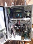
Here is a photo of my existing ECommand4 panel (with cover removed). In the top section you can see my existing ECommand4 board/display; it will stay there. In the top right you can see the relays I added for (1) Waterfall (2)(3) Stenner pumps acid & chlorine. The Stenner pump relays are temporary; they will be moved into the high voltage section. I put those up there yesterday as I just completed adding my acid stenner pump today. Both stenner pumps will be run by the sprinkler controller (seen mounted on the door) until eventually controlled by my new Pool Controller.

20190709_135505.jpg

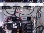
A closeup of the area where I will add the new high voltage relays. Three are shown and I have taken out one; but there is room for a total of eight. I will run control wires from my new controller box to this set of relays for the high voltage control.

20190709_135533.jpg

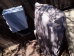
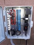
The new controller box mounted on the wall “near” the existing ECommand4 box (which is covered).

20190709_141611.jpg

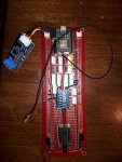
The new Pool Controller board. Photon on the top, RS485 controller hanging to the left, ADS1115 A2D expander in the middle, MCP23017 16 I/O Port Expander on the bottom, wireless antenna is the wire hanging out by itself. Various connectors for the sensors and voltage sources.

20190703_093734.jpg

Mounted in the new panel. The relays are still totally unused at this point, they will be used mostly for control outputs. The only thing the board does currently is receive sensor inputs. Notice I have one of the DS18B20 temperature devices coiled up inside the bottom left of the case currently…that will change to a board mounted version once I order it. The power strip and power supplies are temporary at this point; I haven’t decided exactly how I will permanently attach/generate the voltages I will need.

20190707_182932.jpg

The next major step is to combine all my sensor software “sketches” into a single photon program that will update my google spreadsheet with ALL sensor data. I’ll give some updates on the sensor data collection and after that I’ll probably fool around with the sensor data for awhile before tackling the control section (pump & valve control/ scheduling/ lights control). I might even revisit the android phone app…not yet sure.
 
Last edited:
Now that is just COOL... I dig the PVC pipe cable management! I gotta try that next time I setup an IT closet.:goodjob:
Haha...pvc is my duct tape. I do use it for a lot of things.

ETape Testing Update:

I finished installing my second Stenner Pump today for acid with a Stenner #2 (10gal/day) dispersal tube. I also switched out my Stenner Pump chlorine dispersal tube from a #2 (10gpd) to a #3 (22gpd).

I tested the flow rate of the acid setup by putting 1 gallon of water in the tank. My ETape sensor measurement showed .99 gallons in the tank. I ran the Stenner pump for 30 minutes and measured 32oz (exactly .25 gallons) of water dispersed during that time (roughly 1.1 oz/min). My ETape sensor acid measurement showed exactly .75 gallons remaining...Perfect! Best of all, I could see the acid level (actually water in this test) going down minute my minute.

Do I really need that sort of precision...not really...but it sure is AWESOME!

My test on the chlorine tank: previously I had a #2 tube and had measure at 1.1oz/min dispersal. My new #3 tube gives me about 2.2oz/min dispersal. The number test on the chlorine ETape showed a slight non-linearity for the region I was measuring. The ETape sensor output showed 49oz dispersed when there was actually 54oz dispersed. I did notice a couple of regions like this when I tested the ETapes before the install...the good news is that they get back on track and are never that far off from reporting the actual tank liquid volume, within a couple percent.

A volume check for amount of liquid dispersed is a "check/alert" that I am planning for both acid and chlorine. This won't catch all problems with holes in the stenner lines, but it would have caught the problem I had last time when my chlorine line cracked on the suction side and "sucked air" the entire time, never actually dispersing the chlorine. I'm still thinking about the pressure side....

EDIT: Do NOT use Milone ETapes (even the chemical hardened versions) in muriatic acid tanks...the acid starts degrading the resistive properties immediately. The jury is still out on use in a chlorine tank but so far it is holding up. The owner of Milone is considering a change that may fix this for the future but has not made it so far.
 
Last edited:
9) Why So Many Pressure Sensors?

Why do I have four PSI transducers…don’t systems usually have just one… on the filter?

This was an idea that I thought about during the time I was working on my In-Floor-Cleaning-System (IFCS) thread. I realized how important PSI was for my IFCS. But, I have also thought about some other ideas and would love to hear any input on issues/expansion of these ideas. I will be testing some of these ideas out and figuring out whether I want to move forward with them and/or what kind of response/alert they should automatically generate.

To recap, I have four PSI sensors throughout my system…one on the pump vacuum side, one on the pump pressure side, one on the filter, and one on (actually close) to my IFCS manifold. What good are they? Here is where I am headed with these.

Pump Vacuum Side
  • Give alerts that the skimmer basket needs clearing
  • Give alerts that the pump basket needs clearing
  • Monitor the position of my skimmer/main drain “valve”…the PSI will indicate where the suction is drawing “from”. This is a bit complicated because I actually don’t have a valve there, I have what’s referred to as a “spaceship diverter” in my skimmer. I won’t get into details here, but I have a method to control where I suction the water from (skimmer or main drain). This gauge will monitor the "success" of that mechanism.
Pump Pressure Side
This is probably redundant to the “filter” pressure gauge, but it was an existing spot that I could plug a transducer in. My only idea to date has been to use the pump vacuum side pressure and the pump pressure side pressure to calculate a dynamic GPM.

I have a FlowVis in my system and would compare this dynamic calculation to that given by the FlowVis. If the dynamic gpm calculation is close to the FlowVis, than I will use it, dynamically, to record GPM numbers.

I realize that “knowing your gpm” is not a popular topic for this site. But for me, it has been invaluable. You see, the only way to calculate actual Energy Factor of our very expensive VSPs is to know the GPM and the watts of the VSP at any given RPM. Just having a VSP and operating at a low RPM or a low watts value doesn’t mean you are taking full advantage of it. Something as simple as having the wrong size wall return nozzles can seriously impact your energy efficiency…and you may never know without checking.

Anyway, that’s what I have found out, and why I like to know my GPM.

GPM is also important for systems with IFCSs like mine because of another reason…it’s a dirty word: TURNOVER. Turnover is actually somewhat important for the operation of most IFCSs. The popups stir up the dirt/debris and must “filter” it out. Turnover is a part of that equation.

Filter Pressure Gauge
Obviously when a filter gets dirty, the filter pressure increases. This will give an indication when your filter needs cleaning. Every advanced automation system and their mother should have this one, haha.

In-Floor-Cleaning-System (IFCS) Manifold
Most don’t have IFCSs, of course, but I really like mine, and mine is very cheap to run. Here is what I am going to use this PSI gauge to determine:
  • Monitoring cleaning cycle time: how long it takes popups to completely rotate around the pool once. Changes in this value can indicate a problem with the gear mechanism.
  • Monitoring individual zone pressures. Occasionally, I have a popup loosen and come out, this PSI gauge will immediately give an indication that this has occurred.
  • Monitoring pressure at the IFCS manifold, make sure it is at my target(s) for popup operation
  • Controlling pressure at my IFCS manifold. I’m considering experimenting with feedback from this PSI gauge to “tweak” a valve to any intermediate spot (not fully open or fully closed). I have found a significant advantage for my IFCS by doing this manually (a one-shot permanent valve tweaking), and am considering expanding this method to allow it to be used for more than one IFCS manifold pressure “target” AND be done automatically.
GENERAL
In general, knowing the pressures, rpm, watts for specific operating conditions/configurations is something that can be “compared” to known good values. Deviations by more than TBD percent/value on a particular parameter could indicate a problem, perhaps serious, in the system. I am planning on setting up a table of these values for each common operating condition to use as a comparison.

My EcoStar pump failed last year and I don’t know how many days it was actually failing before I found it. It thought it was running (and if my stenner pumps had been installed at the time, they would have thought so too), but it wasn’t. Monitoring ANY PSI parameter in a system probably would have caught that problem.

Of course, catastrophic failures like pipes breaking can also be detected immediately. The system can easily be shutdown.

Anyway, that’s where I am headed with some of this PSI sensor information. Is it overkill? Possibly, but as I have said many times: I am in this for fun, and to me this kind of experimenting IS fun, haha. Additional PSI transducers are also incremental in effort/cost...in the overall picture, it costs about the same to implement one OR four.
 
Last edited:
  • Like
Reactions: MyAZPool
A mini-update. I was excited by my new acid Stenner pump installation and tested my chems this morning to see if it went as expected. pH level was right on expectation with a 11oz injection. However the chlorine level was low...4.0, not good to start out at with a full sunny day ahead.

I went to my google spreadsheet (my photon is currently loaded with the ETape sensor program) and saw that NO chlorine was injected last night. Out at the pad I discovered that I had left my sprinkler timer controller (currently does both acid and chlorine) on the “run timer menu item” for the acid control . You can actually see it in the picture I posted earlier, haha. This resulted in the acid being dispersed, but no chlorine.

Makes me wonder if I should increase prioritization of acid/chlorine control for my new controller...
 
  • Like
Reactions: MyAZPool
WOOOOOOW!!!
Impressive project!!! (you really have even more A-OCD* than me ;)

A few comments:
- 5 temperature is really needed!!!? Even clorine and acid tank?
- PSI probes seems to be very useful. Could be great to have a digital one-wire version (like DS18B20) instead of analog.
- I am overwhelmed about so many sensor you have (even rpm and watts of pumps!!!)
- I have seen "remaining" orange idicators very useful. I have think only one about filtering cycles in recirculation times (i.e. notify me when water has been filtered 50 recirculation times, to clean filters, etc.)
- I have seen level sensor bands for tanks, but not for water pool level. For me, remaining tank can be aproximately calculated with time system has been injected in pool, but water level in pool is really unpredictable. At this point, have you seen ultrasonic sensors? (i.e based on waterprof JSN-SR04T i.e Aihasd JSN-SR04T V2.0 Transductor ultrasónico Impermeable Sensor Módulo de medición de Distancia: Amazon.es: Electrónica)


* Automation Obsessive Compulsive Disorder
 

Enjoying this content?

Support TFP with a donation.

Give Support
Thread Status
Hello , This thread has been inactive for over 60 days. New postings here are unlikely to be seen or responded to by other members. For better visibility, consider Starting A New Thread.