
Main filter pump breaker tripped
- Thread starter James L.
- Start date
You are using an out of date browser. It may not display this or other websites correctly.
You should upgrade or use an alternative browser.
You should upgrade or use an alternative browser.
I bought a Whiperflo VST pump for my main filter pump. The pool builder guy spoke to a Pentair rep. and he said this would be a perfect, drop-in replacement. I installed it. It is connected to power at the Easytouch control box, but the RS-485 Automation Wiring cable is not connected.
1-- Can I manually turn this pump on at the pump controls, so I can have the pool filter running?
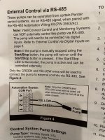
2--Can anyone tell me how to wire the new automation cable to the Easytouch? The installation guide says when paired with the RS-485 cable, connect the yellow and green wires ONLY to the Automation System COM Port, at the #2 and #3 terminals. There are already two green wires and two yellow wires connected to those terminals.
1-- Can I manually turn this pump on at the pump controls, so I can have the pool filter running?
2--Can anyone tell me how to wire the new automation cable to the Easytouch? The installation guide says when paired with the RS-485 cable, connect the yellow and green wires ONLY to the Automation System COM Port, at the #2 and #3 terminals. There are already two green wires and two yellow wires connected to those terminals.
- Jun 24, 2021
- 16,592
- Pool Size
- 29000
- Surface
- Vinyl
- Chlorine
- Salt Water Generator
- SWG Type
- CircuPool RJ-60 Plus
Yes. If it has power, fire it up!1-- Can I manually turn this pump on at the pump controls, so I can have the pool filter running?
Where do those wires go?There are already two green wires and two yellow wires connected to those terminals.
COM Port. Larger cable goes to Salt Surge board. Smaller cable goes to Antenna.
I remembered at the last moment that I cannot run the pump for up to 24 hrs to let the PVC cement set.
I remembered at the last moment that I cannot run the pump for up to 24 hrs to let the PVC cement set.
Attachments


- Jun 24, 2021
- 16,592
- Pool Size
- 29000
- Surface
- Vinyl
- Chlorine
- Salt Water Generator
- SWG Type
- CircuPool RJ-60 Plus

Just saw on another post that single speed pump is wired to a relay, but VST is not. VST needs constant power, so I don't know where the red and black 240v power wires from the pump should be connected to. So, where?
- Jun 24, 2021
- 16,592
- Pool Size
- 29000
- Surface
- Vinyl
- Chlorine
- Salt Water Generator
- SWG Type
- CircuPool RJ-60 Plus
Connect the pump’s power directly to a dedicated GFCI breaker in the EasyTouch load center or an external breaker panel. You won't use a relay.
Use a two-wire RS-485 communication cable to connect the pump to the EasyTouch COM port to control the pump.
I'm not sure if it standard to connect multiple controls to the com port.
@ajw22 or @Jimrahbe would know.
Use a two-wire RS-485 communication cable to connect the pump to the EasyTouch COM port to control the pump.
I'm not sure if it standard to connect multiple controls to the com port.
@ajw22 or @Jimrahbe would know.
- Jul 21, 2013
- 65,789
- Pool Size
- 35000
- Surface
- Plaster
- Chlorine
- Salt Water Generator
- SWG Type
- Pentair Intellichlor IC-60
Two wires can be placed under each COMM port screw without problems.
You have two open COMM ports on the surge card on the back wall although one is missing the connector. They are circled below in red and yellow.
Use JP4, the red circle, to connect your pump to.

You have two open COMM ports on the surge card on the back wall although one is missing the connector. They are circled below in red and yellow.
Use JP4, the red circle, to connect your pump to.
The green and yellow wires of the RS-485 cable coming from the vst pump connect to the salt surge board, and not the J20 COMM port?
- Jul 21, 2013
- 65,789
- Pool Size
- 35000
- Surface
- Plaster
- Chlorine
- Salt Water Generator
- SWG Type
- Pentair Intellichlor IC-60
Yup, that is what I said.The green and yellow wires of the RS-485 cable coming from the vst pump connect to the salt surge board, and not the J20 COMM port?
The surge board connects to J20 so the comm will get there.
Thanks!
So, replacing single speed Whisperflo and installing Whisperflo VST:
1--Remove black and red wires from the pump relay and connect the pump's black and red wires directly to pump breaker.
2--Connect green and yellow wires from automation cable from pump to COMM port on surge board.
3-- Do you keep all the wires connected to the J20 COMM port (two reds, two yellows, two greens, two blacks, coming from the salt board and the antenna) alone? Leave them connected right whwere they are?
4--Do you keep the white and yellow wires (coming from the large transformer)connected to the relay?
5--Anything else?
Last edited:
- Jul 21, 2013
- 65,789
- Pool Size
- 35000
- Surface
- Plaster
- Chlorine
- Salt Water Generator
- SWG Type
- Pentair Intellichlor IC-60
Thanks!
So, replacing single speed Whisperflo and installing Whisperflo VST:
1--Remove black and red wires from the pump relay and connect them directly to pump breaker.
No. Slide the black and red wires from the pump under the other side of the LINE screws.
The relay LINE screws will then have two wires - one from the circuit breaker and one from the VST pump.
2--Connect green and yellow wires from automation cable from pump to COMM port on surge board.
Yes.
3-- Do you keep all the wires connected to the J20 COMM port (two reds, two yellows, two greens, two blacks, coming from the salt board and the antenna) alone? Leave them connected right whwere they are?
Leave them as is.
4--Do you keep the white and yellow wires (coming from the large transformer)connected to the relay?
Yes, to the LOAD side of the relay.
Do you understand the relay screws LINE and LOAD?5--Anything else?
Relays have four screws - LINE1, LOAD1, LINE2 LOAD2.
I didn't until you just told me.
Sorry, could you tell me specifically (Wiring for dummies) what wires connect to each screw, left to right (Line1, Load1, line2, load2)?
Sorry, could you tell me specifically (Wiring for dummies) what wires connect to each screw, left to right (Line1, Load1, line2, load2)?
- Jul 21, 2013
- 65,789
- Pool Size
- 35000
- Surface
- Plaster
- Chlorine
- Salt Water Generator
- SWG Type
- Pentair Intellichlor IC-60
- Jul 21, 2013
- 65,789
- Pool Size
- 35000
- Surface
- Plaster
- Chlorine
- Salt Water Generator
- SWG Type
- Pentair Intellichlor IC-60
This was discussed with you in posts 18-20.I didn't until you just told me.
Sorry, could you tell me specifically (Wiring for dummies) what wires connect to each screw, left to right (Line1, Load1, line2, load2)?
Screws from left to right are LINE1, LOAD1, LINE2 LOAD2.
CB wires with the blue tape are on the left side of LINE1 and LINE2 screws.
Pump black and red wires are on left side of LOAD1 and LOAD2 screws.
black and red wires need to be moved to under right side of LINE1 and LINE2 screws.
White and yellow wires stay as is.
Screw 1: black wire with blue tape goes to pump breaker.
Screw 2: black wire goes through conduit to pump; white wire goes to large transformer
Screw 3: red wire with blue tape goes to pump breaker
Screw 4: red wire goes through conduit to pump; yellow wire to large transformer
Screw 2: black wire goes through conduit to pump; white wire goes to large transformer
Screw 3: red wire with blue tape goes to pump breaker
Screw 4: red wire goes through conduit to pump; yellow wire to large transformer
Attachments


- Jul 21, 2013
- 65,789
- Pool Size
- 35000
- Surface
- Plaster
- Chlorine
- Salt Water Generator
- SWG Type
- Pentair Intellichlor IC-60
See post 55 above.Screw 1: black wire with blue tape goes to pump breaker.
Screw 2: black wire goes through conduit to pump; white wire goes to large transformer
Screw 3: red wire with blue tape goes to pump breaker
Screw 4: red wire goes through conduit to pump; yellow wire to large transformer
- Jul 21, 2013
- 65,789
- Pool Size
- 35000
- Surface
- Plaster
- Chlorine
- Salt Water Generator
- SWG Type
- Pentair Intellichlor IC-60
TFP is a member supported 501(c)3 non-profit that is volunteer staffed and has no ads. Your support keeps the servers running so we can be here to help you. It would be helpful if you considered supporting TFP so we can be here to help in the future....Got it. Thank you for your time and patience.

Become a TFP Supporter
Help Support TFP Trouble Free Pool is run by a dedicated group of volunteers that … Read more…
 www.troublefreepool.com