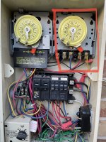
Hi folks, happy new year. Did try and do some research but it went out the door when I removed the cover for the intermatic timer. In the attached the pic, the timer on right with the red box around the pic is the one that has gone bad and only controls the polaris cleaner. However the timer on the right needs to be on in order for the cleaner to run. I have a few questions:
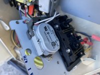
1. What kind of timer do I need? Is the one in the pic a T104?
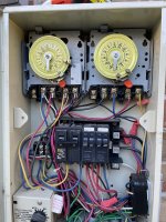
2. Do I simply remove the connections and just add them exactly like they are back on the new timer?
3. Any other issues you see that I may run into?
Thanks
1. What kind of timer do I need? Is the one in the pic a T104?
2. Do I simply remove the connections and just add them exactly like they are back on the new timer?
3. Any other issues you see that I may run into?
Thanks