The house we moved into about six months ago has an EasyTouch panel, with an IntelliFlo, IntelliChlor, BoostRite, and 120V IntelliBrite lights managed by it. There have been a couple of times where the 20A GFCI breaker will trip, causing the pump to shut down. So far I've always been home to reset it, but I fear the day it happens while we're away on vacation and chlorine production comes to a halt.
I was doing some homework online to see if things were wired properly, and some of it seems a little fishy. Basically it is set up like this:
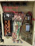
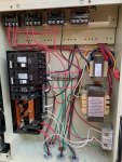
- EasyTouch panel has two breakers in it.
- One breaker is a 240V 20A Siemens GFCI. It has two sets of wires coming out of it. One set goes directly to the IntelliFlo, and the other set goes to the "Pool" relay. This pool relay appears to then feed power to the booster pump relay, and the IntelliChlor transformer. I assume this is to ensure neither of those operate without the IntelliFlo operating.
- The other breaker is a 120V 20A Cutler Hammer non-GFCI, again with two wires coming out of it. One wire goes to a GFCI outlet mounted on the side of the enclosure, which then feeds/protects the relay for the IntelliBrite lights. The other wire goes to the system transformer for the EasyTouch logic boards.
To me this seems a little weird for a few reasons.
- Double tapping circuit breakers is generally a bad thing unless they're listed for it. Pretty sure neither of these are.
- The IntelloFlo manual states that the pump should be on its own dedicated breaker.
- Having both the IntelliFlo and BoostRite on the same breaker seems bad, since I believe the max combined current draw would be ~21A (plus the tiny amount drawn by the IntelliChlor).
- Also not sure if the 20A GFCI breaker is plain old Siemens, or if it's the special Pentair branded version. Is there a way to tell?
My gut feeling is that I should:
1. Remove the second set of feed wires from the IntelliFlow breaker that go to the pool relay, and run them from a separate 240V 15A or 20A GFCI breaker. This would mean the IntelliChlor and BoostRite would be powered/protected by their own GFCI breaker, and the existing 20A GFCI breaker would ONLY power the IntelliFlo. The EasyTouch relay logic would be used to ensure the IntelliChlor and BoostRite don't operate without the IntelliFlo operating. But what happens if the IntelliFlo pops its breaker. Would those other two items continue to operate?
2. Remove the double tapped wiring from the 120V breaker, such that both the IntelliBrite transformer AND the EasyTouch logic boards would be protected by the external GFCI outlet.
Curious what everyone else thinks. Attached is a photo of the panel interior. To avoid any confusion, there are two hots (black and red) running to the pool lights. One for each light. Not sure why they did that, instead of just running a single hot and wire nutting together the two lights in the elevated junction box.
I was doing some homework online to see if things were wired properly, and some of it seems a little fishy. Basically it is set up like this:
- EasyTouch panel has two breakers in it.
- One breaker is a 240V 20A Siemens GFCI. It has two sets of wires coming out of it. One set goes directly to the IntelliFlo, and the other set goes to the "Pool" relay. This pool relay appears to then feed power to the booster pump relay, and the IntelliChlor transformer. I assume this is to ensure neither of those operate without the IntelliFlo operating.
- The other breaker is a 120V 20A Cutler Hammer non-GFCI, again with two wires coming out of it. One wire goes to a GFCI outlet mounted on the side of the enclosure, which then feeds/protects the relay for the IntelliBrite lights. The other wire goes to the system transformer for the EasyTouch logic boards.
To me this seems a little weird for a few reasons.
- Double tapping circuit breakers is generally a bad thing unless they're listed for it. Pretty sure neither of these are.
- The IntelloFlo manual states that the pump should be on its own dedicated breaker.
- Having both the IntelliFlo and BoostRite on the same breaker seems bad, since I believe the max combined current draw would be ~21A (plus the tiny amount drawn by the IntelliChlor).
- Also not sure if the 20A GFCI breaker is plain old Siemens, or if it's the special Pentair branded version. Is there a way to tell?
My gut feeling is that I should:
1. Remove the second set of feed wires from the IntelliFlow breaker that go to the pool relay, and run them from a separate 240V 15A or 20A GFCI breaker. This would mean the IntelliChlor and BoostRite would be powered/protected by their own GFCI breaker, and the existing 20A GFCI breaker would ONLY power the IntelliFlo. The EasyTouch relay logic would be used to ensure the IntelliChlor and BoostRite don't operate without the IntelliFlo operating. But what happens if the IntelliFlo pops its breaker. Would those other two items continue to operate?
2. Remove the double tapped wiring from the 120V breaker, such that both the IntelliBrite transformer AND the EasyTouch logic boards would be protected by the external GFCI outlet.
Curious what everyone else thinks. Attached is a photo of the panel interior. To avoid any confusion, there are two hots (black and red) running to the pool lights. One for each light. Not sure why they did that, instead of just running a single hot and wire nutting together the two lights in the elevated junction box.