Ignition Control Board Part Question? Part # FDXLICB1930 Kit

tstex

Silver Supporter
Aug 28, 2012
2,177
Houston, TX
Getting ready to swap out the control panel board and display board.

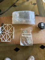
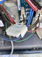
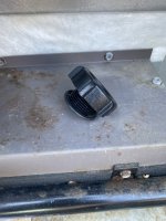
The display board is EZ-PZ. Based on enclosed pic, what is the white plastic piece at 9 O’clock? Also, besides just following common sense on plug, terminals & wiring swap/outs, are there any steps i need to be aware of to make the install go smoother? Just looking for any “make sure you watch out for this” kind of steps?

thank you and pls advise,
Tstex
 

Attachments

  • EC27C756-CBDB-4514-BB8B-CFE01C4367CC.jpeg
    EC27C756-CBDB-4514-BB8B-CFE01C4367CC.jpeg
    572.7 KB · Views: 6
Last edited:
Heater is working fine now…didn’t see any burned out or bad looking components on either board ? Am i missing something?

Did find one 120v terminal plug that was not being used (pic 1) and a plug (pic 2). What are these 2 parts for?
 

Attachments

  • 04F14875-8150-4D41-BB06-F5BAE15C36C9.jpeg
    04F14875-8150-4D41-BB06-F5BAE15C36C9.jpeg
    338.8 KB · Views: 5
  • F9827A4F-F4BD-4E7B-AAAC-D2D99BB64D8B.jpeg
    F9827A4F-F4BD-4E7B-AAAC-D2D99BB64D8B.jpeg
    378 KB · Views: 5
Is your heater powered by 120V or 240V?
 
The white piece looks like it is a holder for the circuit board.

It is probably only used on a limited number of models.

1633543775153.png
The heater can be wired for 120 or 240.

So, you only use the plug that corresponds to the supply voltage.

The drain plug went at the red dot.

There is now a pressure relief installed in place of the plug.

1633544121551.png
1633544302812.png
 
Thanks Allen & James. Yes, since it's wired 240V, they left the 120V terminal inside the unit.

On the plug, that was awesome James that you pulled a previous pic of my heater/piping area and marked it w a red dot...talk about customer service :)

As mentioned in post 1, I did not see any major problems w the boards on either side, except what "looks like small foaming" on the Ign Control Board where the wiring harness from the display board connects. If you guys would like, I could post pics of both boards, front and back, and see if we can identify any corrosion, burn marks or other.

Again, thank you very much for your continued support and help, tstex
 
On the plug, that was awesome James that you pulled a previous pic of my heater/piping area and marked it w a red dot...talk about customer service
For the picture, I was going to either send a drone for a flyover or maybe repurpose an NSA micrometer resolution satellite, but luckily, you had posted a picture earlier and I did not need to do either of those two things.
 
Thanks Allen & James. Yes, since it's wired 240V, they left the 120V terminal inside the unit.

On the plug, that was awesome James that you pulled a previous pic of my heater/piping area and marked it w a red dot...talk about customer service :)

As mentioned in post 1, I did not see any major problems w the boards on either side, except what "looks like small foaming" on the Ign Control Board where the wiring harness from the display board connects. If you guys would like, I could post pics of both boards, front and back, and see if we can identify any corrosion, burn marks or other.

Again, thank you very much for your continued support and help, tstex
Many times when I replace these boards and there are no outward signs of issues. As for the plastic piece you asked about earlier, Hayward finally realized that if someone is in the unit and presses on the board it will touch the metal and short the board out. So they added the plastic piece for the board to be snapped into so that it won't come in contact with the metal. As for the 120/240 plug, I know I always leave both just in case someone for whatever reason switches voltage of the unit. From the factory the 240 plug is plugged in.
 
For the picture, I was going to either send a drone for a flyover or maybe repurpose an NSA micrometer resolution satellite, but luckily, you had posted a picture earlier and I did not need to do either of those two things.
Pls send link to repurposed satellite / LOL Thank you Paul for the explanations.

Ok, I have another problem. After a zoom meeting, I came outside and my heater was running - I did not initiate it, as I have traditionally done.

The heater Icon lit light was not displayed on my in-home remote keypad, and when I looked at my outside control panel, the heater icon was not lit there either. Before replacing the parts, I typically initiated the heater by using my inside remote: I would hit SPA MODE, FILTER pump, then after 10 secs, hit HEATER and the heater would come on 10 sec's later [the built in delay].

When I powered up the heater, I did not see any of the typical display codes when the heater was not supposed to operate. I saw 78, and Standby Light was lit. The heater would not start by hitting the controller keypad as I normally we initiate, I had to change the mode from Standby to SPA, then increase the temp, which I did to 99.

When I changed out the Ign Control Board, did this do something to my prior settings that pertains to my settings for my Spa and how I operate it?

thank you and pls advise
 

Enjoying this content?

Support TFP with a donation.

Give Support
  • Like
Reactions: tstex
This is great James...thank you. That "bo" mode is not what I have seen and that's the problem...it's a local or at the heater operations mode.

I will start the process above and see if I can get it in 'bo" mode and post back - thanks again !!
 
  • Like
Reactions: JamesW
Thread Status
Hello , This thread has been inactive for over 60 days. New postings here are unlikely to be seen or responded to by other members. For better visibility, consider Starting A New Thread.