Electrical Help Needed for Hayward Super Pump 1.5HP 230V Dual Speed w hi-lo switch attached

Paul Holzer

New member
Apr 20, 2019
4
Chicago
Need help with Electrical Diagrams on how to wire a new Hayward Super Pump 1.5HP 230V with Hi-Lo Switch Attached.
It's replacing an existing Dual Speed Hayward Super Pump 230V.
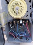
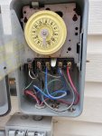
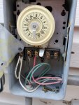
The pump is attached to Intermatic Timer (T103R - and has 4 wires from the box to the pump, (Black, Blue, Red and Green).
I would like to know what I need to do to bypass the hi-lo switch on the back of the pump and keep utilizing the Intermatic Timer.
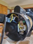
The Switch on the Pump has Yellow, Black and White Wires. Black is going to terminal 4, Yellow is going to terminal 2, not sure where white it going.
Any help would be appreciated.
 
Paul,

You can't use the T103... You need a dual speed timer.. It is very important that you never apply power to the high speed and low speed inputs at the same time and that is what the 2-speed timer does.

Thanks,

Jim R.
 
Jim, that's what I have used for the past 10 years without any issues until my pump gave out last week. I order a new pump, but this one now comes with a hi-lo switch attached, so I am loking for someone to provide recommendation on bypassing the switch on the back of the pump ad utilizing the existing 4 wire configuration from my Intermatic Timer (that is configured for hi/lo speed based on timer).

I have attached pictures of the wiring on the pump and the Intermatic and would appreciate any help; in recommending what wire I should remove from the switch and connect from the Intermatic to the ports on the pump.

Thanks in advance.
 

Attachments

  • 20190420_120208.jpg
    20190420_120208.jpg
    434.6 KB · Views: 16
  • 20190420_125421.jpg
    20190420_125421.jpg
    365.2 KB · Views: 19
Paul,

Ok that just means you do not have a T103 timer if it has been working with a 2-speed pump before it has to be a T106R.. Anyway I now know which color wire does what on the timer, but I need to look the pump up and I have run out of time for today.. I just need some info from you.

1. Can you post a pic of the wiring diagram on the side of the pump.
2. With your old pump, did the timer just turn on the high speed? If not, what happened when you closed the switch?

If no one figures this out tonight, I'll post back tomorrow..

Thanks,

Jim R.
 
Jim, please find attached the wiring diagram from the side of the pump. I have also included a couple of other pictures that show's the wiring from both the T103 and T106.
In answer to your question, the pump would alway's run low speed until the timer kicked in to switch it to highspeed and then back to low speed. It never powerered off unless I switched it off at the breaker (before the timer).

Let me know if you need any additional information and thanks for your help.
 

Attachments

  • 20190422_113237.jpg
    20190422_113237.jpg
    214.1 KB · Views: 19
  • 20190422_113243.jpg
    20190422_113243.jpg
    503.5 KB · Views: 14
  • 20190422_115224.jpg
    20190422_115224.jpg
    517.6 KB · Views: 11
  • 20190422_115244_001.jpg
    20190422_115244_001.jpg
    413.8 KB · Views: 12
You remove and discard the yellow and black jumper wires that are connected to the switch.

Disconnect the white wire from the switch and connect it to the bottom terminal (#3,4).

From the timer, connect black to #1, red to #2 and blue to #3,4.

Green goes to ground. Green screw.

The end result should be that when you select high speed, 240 goes to terminals 1 and 2 with no power to 3/4 and when you select low speed, 240 volts goes to terminals 1 and 3/4 with no power to terminal 2.

Terminal #1 is common. #2 is high and #3/4 is low (after reconfiguration of the wires).

If you find that high and low are reversed, you can switch the red and blue wires.

The switch has 3 terminals. The center terminal is power in and power goes out on one of the outer terminals depending on which way the switch is pointing. In this case, we are not using the switch and no wires will be connected to the switch.

The white wire goes to the low speed windings. That's why #3,4 becomes low speed when the white wire is connected.
 
Last edited:
Paul,

Well I hate to admit defeat, but there is a white wire that I can't quite figure out where it goes.. It might not make any difference, but I'd hate to give you advice that blows up your new pump..

I'm going to PM a couple of pump guys and see what they have to say...

I wrote this but i guess I never posted it...

Thanks JamesW great post,

Jim R.
 
We are glad you have found our information helpful. Please, if you can, consider making a donation to TFP.

We are staffed by volunteers and are registered as an IRS 501 (c) (3) charity and donations are what keeps the forum operating without advertisements.

Support TFP!
 

Enjoying this content?

Support TFP with a donation.

Give Support
Thread Status
Hello , This thread has been inactive for over 60 days. New postings here are unlikely to be seen or responded to by other members. For better visibility, consider Starting A New Thread.