Check the voltage and amperage of the motor while operating and compare the results to the motor label.

Determine Fan Speed without seeing it!
- Thread starter setsailsoon
- Start date
You are using an out of date browser. It may not display this or other websites correctly.
You should upgrade or use an alternative browser.
You should upgrade or use an alternative browser.
- Oct 25, 2015
- 5,147
- Pool Size
- 25000
- Surface
- Plaster
- Chlorine
- Salt Water Generator
- SWG Type
- CircuPool RJ-60 Plus
Thanks James, it runs well below the rated amps. Runs .44 amps vs .68 rated. Does this sound right? *** Edit*** Didn't actually check voltage. Will do that tomorrow. Thanks so much for the suggestions!Check the voltage and amperage of the motor while operating and compare the results to the motor label.
Last edited:
- Oct 25, 2015
- 5,147
- Pool Size
- 25000
- Surface
- Plaster
- Chlorine
- Salt Water Generator
- SWG Type
- CircuPool RJ-60 Plus
Allen,Considering you said it It popped and sparked with a vengeance I would being closely examing the wires and connectors. It is a tedious job but checking continuity of each wire and connector. My thinking is maybe some wire has a loose pin or is hanging on by a few strands of copper.
Thanks. I've spot checked them all and checked closely all the grounds. But I think I need to do this more meticulously as you pointed out. That'll be tomorrow's focus.
Chris
I would also check every molex connector. I've on more than one occasion found when you push the molex connector together, if they don't mate for some reason it will actually push one side back and only makes contact at the very tip of that wire in the molex connector. A slight movement will disconnect the minimal contact and leave you with an open wire. When you check for this you have to check each wire at both sides because externally all looks perfect.
swamprat69
Well-known member
Flame is sensed from ignitor through flame to burner and/or screen ground. If ignition module and ignitor are both new, the only variables that should effect flame sensing are how well the burner assembly/screen is grounded and whether the flame is hitting both the ignitor and the burner assembly/screen correctly to sense the flame. Check burner/screen ground. Check gas orifice. I don't know if the burner and the burner screen are one piece or separate, but it seems if the ignitor is outside of the burner/screen assembly that the flame is actually sensed between the ignitor and the burner screen because the gas/air mixture between the burner and the burner screen would not be lit. If possible check that the outside of the burner screen is clean bare metal and grounded well. Check the inside of the burner for dirt/blockage. If possible check the burner slots/orifices for blockage/cleanliness. I have worked on both residential and commercial units with drum/cylindrical combustion chambers and negative pressure gas valves and they seem to have some specific areas with problems. Most notably corrosion/dirt in the combustion chamber and also around fasteners for various parts attached to the combustion chamber.
- Oct 25, 2015
- 5,147
- Pool Size
- 25000
- Surface
- Plaster
- Chlorine
- Salt Water Generator
- SWG Type
- CircuPool RJ-60 Plus
I would also check every molex connector. I've on more than one occasion found when you push the molex connector together, if they don't mate for some reason it will actually push one side back and only makes contact at the very tip of that wire in the molex connector. A slight movement will disconnect the minimal contact and leave you with an open wire. When you check for this you have to check each wire at both sides because externally all looks perfect.
Great tip! I'll check. Thanks!
- Oct 25, 2015
- 5,147
- Pool Size
- 25000
- Surface
- Plaster
- Chlorine
- Salt Water Generator
- SWG Type
- CircuPool RJ-60 Plus
Swamp,*** Edit - was missing the second photo... operator error***
Flame is sensed from ignitor through flame to burner and/or screen ground. If ignition module and ignitor are both new, the only variables that should effect flame sensing are how well the burner assembly/screen is grounded and whether the flame is hitting both the ignitor and the burner assembly/screen correctly to sense the flame. Check burner/screen ground. Check gas orifice. I don't know if the burner and the burner screen are one piece or separate, but it seems if the ignitor is outside of the burner/screen assembly that the flame is actually sensed between the ignitor and the burner screen because the gas/air mixture between the burner and the burner screen would not be lit. If possible check that the outside of the burner screen is clean bare metal and grounded well. Check the inside of the burner for dirt/blockage. If possible check the burner slots/orifices for blockage/cleanliness. I have worked on both residential and commercial units with drum/cylindrical combustion chambers and negative pressure gas valves and they seem to have some specific areas with problems. Most notably corrosion/dirt in the combustion chamber and also around fasteners for various parts attached to the combustion chamber.
Lot of good stuff to check here. Thanks so much. I have removed the burner tube and it was in pretty good shape but I sanded it clean and shiny anyway. The screen is as you suspect. Here's a photo I took (before cleaning):

Here's the bottom that is close to the bottom of the firebox (also before cleaning):

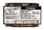
I also measured the voltage at the test posts on the Fenwel controller. Never gets close to the 2 volts or so. I measured a max of 150 mv after the flame lights, then it drops down to a couple mv before the gas valve closes. I'm really wondering if maybe the fan is running too slow. Would definitely make the flame low. My next test is to parallel the flame sense outside the fire box. I'm thinking to tie on the the black wire on the igniter with a nail at the end of a board and then to run a ground wire from by blow torch to the ground on the ignition control board. Then when the gas valve opens put the nail in the flame. If this makes the blower stay on then maybe my flame is actually too small and more evidence I should buy the new blower. Also, I definitely know the connector going back to the blower from the ignition module (terminals F1 and F2) got totally fried.
Any thoughts on this approach?
Chris
Attachments

Last edited:
swamprat69
Well-known member
Most problems with squirrel cage type blowers not moving enough air (including residential furnace blowers) have to do do with dirt buildup in the cup of the vanes reducing the the amount of airflow. You could check your 11 vanes for dirt buildup and clean with a screwdriver and/or brush if needed. If they are dirty and you clean them, you may need to readjust the negative gas flow to the new air volume.
- Oct 25, 2015
- 5,147
- Pool Size
- 25000
- Surface
- Plaster
- Chlorine
- Salt Water Generator
- SWG Type
- CircuPool RJ-60 Plus
Thanks Swamp, I'll take a closer look. Don't remember it looking dirty but all I really did was count the blades.
Chris
Chris
swamprat69
Well-known member
Just one caveat on your cleaning of the burner/screen. If you used silica carbide sandpaper, silica is an electrical insulator and you would need to wipe it all down to remove it in order to get good electrical conductivity.
- Oct 25, 2015
- 5,147
- Pool Size
- 25000
- Surface
- Plaster
- Chlorine
- Salt Water Generator
- SWG Type
- CircuPool RJ-60 Plus
Yesterday, I did some additional testing as follows:
Chris
- I clipped the test posts on the Fenwel to video the voltage during the 7 sec ignition phase. The voltage never gets beyond 40 or so mv.
- Previously, I had thought it was 150 mv. But it's hard to see on a digital reading because the display changes so quickly. This time I videoed it then replayed in slow motion. It should go up to over 2v.
- So I set up my test of the ignition module by tapping into the black wire tab on the Fenwel and connecting this to a nail that I held with a piece of wood. Then I ran a ground wire from the Fenwel ground to the case of a blow torch. After the gas valve opens I put the nail in the flame.
- Essentially, I created a parallel flame and flame sense circuit outside my heater to verify that the ignition module was able to detect a flame sense signal. It didn't work. This could not be the case if there was a 120 vac signal on the flame sense rod. I wondered if I was actually getting voltage to the flame sense leg of my igniter. In the Jxi series heater the igniter is also the flame sense rod.
- Next I checked the flame sense voltage applied to the black wire at the module. It starts at 120 vac as expected but about 2 seconds into the 7 second ignition phase after preheat period the voltage drops to zero. Could be the reason I'm not detecting flame is that there's not a 120 vac signal in the flame that's required to "leak" current to ground?
Chris
Last edited:
swamprat69
Well-known member
swamprat69
Well-known member
I would think that in order to use the ignitor to sense the flame that the ignition module would need to open the neutral to the ignitor while still providing 120v L1 hot to one side of the ignitor and then measure the flame sensing through a switched circuit. It is difficult to tell without the sequence of operation, circuit diagram and thresholds for the Fenwal. If you are measuring your voltage between IGN/120 and IGN/FS I would expect your voltage to drop to 0v during flame sensing and read micro amps at that point instead.
To get a good measurement of the flame current at the test points, you need a good "true-rms" meter that can measure dc volts and dc microamps.
The dc is coming from an ac source, so it's going to pulse and not be a clean signal.
A regular meter uses an averaging method that is not accurate for unusual voltage situations.
The dc is coming from an ac source, so it's going to pulse and not be a clean signal.
A regular meter uses an averaging method that is not accurate for unusual voltage situations.
- Oct 25, 2015
- 5,147
- Pool Size
- 25000
- Surface
- Plaster
- Chlorine
- Salt Water Generator
- SWG Type
- CircuPool RJ-60 Plus
Thanks Swamp. I measured between the black wire connection to the igniter and ground. Starts at zero goes to 122 vac when igniter starts to heat up then stays at 122 'till about 2 sec after the gas valve opens. Then drops to zero. Seems like it should stay at 122 'till the 7 secs are up. Repeats the cycle then on 3 rd attempt goes to lockout mode. Seems like a bad module but it's brand new.I would think that in order to use the ignitor to sense the flame that the ignition module would need to open the neutral to the ignitor while still providing 120v L1 hot to one side of the ignitor and then measure the flame sensing through a switched circuit. It is difficult to tell without the sequence of operation, circuit diagram and thresholds for the Fenwal. If you are measuring your voltage between IGN/120 and IGN/FS I would expect your voltage to drop to 0v during flame sensing and read micro amps at that point instead.
Chris
- Oct 25, 2015
- 5,147
- Pool Size
- 25000
- Surface
- Plaster
- Chlorine
- Salt Water Generator
- SWG Type
- CircuPool RJ-60 Plus
Thanks James, that explains why I get the weird readings. I'll see if anyone I know has a true RMS meter... I videoed the meter and never gets to 100 mv. But not a true RMS meter.To get a good measurement of the flame current at the test points, you need a good "true-rms" meter that can measure dc volts and dc microamps.
The dc is coming from an ac source, so it's going to pulse and not be a clean signal.
A regular meter uses an averaging method that is not accurate for unusual voltage situations.
- Oct 25, 2015
- 5,147
- Pool Size
- 25000
- Surface
- Plaster
- Chlorine
- Salt Water Generator
- SWG Type
- CircuPool RJ-60 Plus
Folks,
You may have see my other post on the heater where I finally found out what was wrong and was able to easily correct it. If not, here's the link. I did want to follow up on the subject technique. I learned it's important to check very carefully what peak you measure. In my case I looked at the peak that calculates out to ~2300 rpm. When I re-checked carefully it appears there is a peak at 620hz that is really the fundamental frequency. How do I know this? There are at least 4 harmonics of this frequency in the spectrum. 620 hz divided by 11 blades then times 60 sec/min gives 3381 rpm, very close to the rated rpm of 3480. Based on my very limited work with this technique I would say after some practice the accuracy is +/- 200 rpm at best and takes some good study to find the fundamental frequency. This is a weakness of this technique. I really did need to go through the entire spectrum to verify I had the real fundamental frequency. My preference would always be to use a real rpm meter. But when you just can't do that because you have an enclosed blower this is the best way I know to measure speed.
I hope this helps.
Chris
Last edited:
Thread Status
Hello , This thread has been inactive for over 60 days. New postings here are unlikely to be seen or responded to by other members. For better visibility, consider Starting A New Thread.