Connecting my Easy Touch 4

timjet

0
Sep 4, 2015
69
Leesburg, FL
Pool Size
15000
Surface
Plaster
I just got an Easy Touch 4 system and have a couple of questions concerning how to connect it electrically.
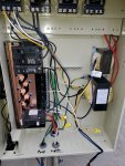
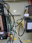
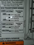
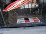
1. The Control Transformer: I connected the black wire to a 15 amp circuit breaker and the violet wire to neutral. Correct?
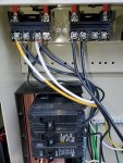
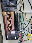
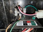
2. The relays. I have a 240 volt single speed pump. I connected the far left terminal (#1) of the filter pump relay to one terminal of the 20 amp duplex circuit breaker. The next terminal (#2) to the right on the filter pump relay I connected to one wire on the pump. The next terminal on the relay (#3) I connected to the other terminal of the duplex circuit breaker and the far right terminal of the relay (#4) I connected to the other wire of the pump. I connected the wire in the electronics bay (upper section of the easy touch) that goes to the filter pump relay to the connection that's labeled "Filter Pump".
3. Pool light. Using the Aux 1 relay I connected the hot wire from the light transformer to the #1 terminal on the relay and a wire from a 20 amp circuit breaker to the #2 terminal of the relay. In the electronics section I connected the wire from the Aux 1 relay to the port labeled Aux 1.

Correct so far??
 
Show us pics of the inside wiring of your ET to check the wiring.

Are you using GFCI CB's for the pump and light?
 
Tim,

So far so good..

Just to nit pick on the lights... Relay pins #1 and #3 are the line or input side of the relay and pins #2 and #4 are the load side of the relay.. It is always best to connect things as they should be so that the next guy does not get fooled.. Having the power applied to Pin #2 and the load on pin # 1 will work, it is just not "right"...

Most people use GFCI protected power for lights, but if you have a transformer for low voltage LED lights, I don't believe that a GFCI is required..

Thanks,

Jim R.
 
Attached are some pictures. Jim, I didn't make it clear, the CB is attached to pin 1 on the relay and the lights to pin 2. I do have transformers for the lights and I will replace the CFCI shown in the pictures with a standard 15 amp CB.
Please check the connections on the SWG transformer and the System Transformer.
 

Attachments

  • 20210201_163200.jpg
    20210201_163200.jpg
    529.7 KB · Views: 20
  • 20210201_163206.jpg
    20210201_163206.jpg
    457.7 KB · Views: 19
  • 20210201_163214.jpg
    20210201_163214.jpg
    501.2 KB · Views: 18
  • 20210201_163220.jpg
    20210201_163220.jpg
    448.8 KB · Views: 15
Tim,

You have the SWCG transformer (yellow and white) wired to the line side of the pump/filter relay.. It needs to be wired to the load side (#2 and #4).. the whole idea here is that the SWCG transformer must not have power unless the pump filter relay is closed.. The way you have it wired the transformer would have constant AC power, which is wrong...

Thanks,

Jim R.
 
Tim,

Tell me about the GFCI at the bottom.. I have never seen a GFCI without a "pig tail" that is connected to the Neutral bus.. What happened to the pig tail???

When a GFCI is used (what I would do) the white wire from the light transformer goes back to the Neutral connection on the breaker and not the Neutral bus..

While I believe a standard breaker can be used to power a light transformer, most people use a GFCI breaker, just to be sure..

The system transformer is wired ok..

Thanks,

Jim R.
 
Thanks Jim, concerning the incorrect wiring for the SWG transformer, I though it was incorrectly wired but was following the diagram on the door of the ET. Picture below. I have corrected it. I believe the diagram is mis-leading.
Concerning the GFIC, the picture I included does not show clearly the pig tail of the GFCI. I have it connected to the neutral bus. I will disconnect it from the neutral bus and connect it to the neutral wire from the transformer.
 

Attachments

  • ET.jpg
    ET.jpg
    337.8 KB · Views: 4
Tim.

The diagram shows what color wires to use for 240 or 120, not where to wire them.. In your pic you have Yellow and White going to the line/input side of the pump filter relay.. They should be connected to the load/output side of the relay.. The Violet/Blue and Back wires are just connected together with a wire nut.

The pigtail from the GFCI breaker goes to the Neutral bus.. The white wire from the light transformer goes back to the neutral connection on the GFCI breaker itself..

Thanks,

Jim R.
 
OK Jim, I think I finally got it. The white pigtail wire on the GFIC goes to the neutral bus. The neutral terminal on the GFIC goes to the neutral wire coming from the light transformer. The load terminal on the GFIC goes to the line terminal (#1) on the Aux 1 relay. The load terminal (#2) on the aux 1 relay goes to the hot or black wire on the lights transformer.
I'm getting there thanks to your help.
I'm plumbing the SWG today and will then start on the gas pool heater. I have no idea how to ellectrically connect that and will start a new thread.
 

Enjoying this content?

Support TFP with a donation.

Give Support
OK, so far so good. Now to connect my Hayward gas heater to my ET. It was formally connected to the simple pool pump timer which is now gone. I have the three 120 v AC wires from the heater. I will use the ET 4 power circuit breaker section to provide the power. So where do I start. I have no manual for the heater. I will connect the valves later, just want to start with the heater and get it working manually before I start on the valves.
 
Tim,

What size breaker feeds your EasyTouch??

I suspect the wires from the heater are for two 120 volt lines that together make up the 240 volts going to the heater. The third wire would be a ground.. If you don't know this to be a fact, then you need to look inside the heater and see where the wires are connected.. What color are the wires? Black, Black, and green or maybe Black, Red and green or ??????

Gas heaters can be run off of 240 or 120, so it would be very important to know how the heater is wired.

Thanks,

Jim R.
 
Figure out what model Hayward heater you have. All the manuals are somewhere on the net. If you cannot find any data plates on the inside doors then post pics of your heater and the wiring.

 
Thanks Jim & Allen, Jim is correct the heater is 240 volts. Picture below shows romex cable but if you look carefully the white normally neutral wire has black tape around it signifying it is the other leg of a 240 volt cable. Whoever installed this pump and heater did that on the 240 v pump too.
So where do I go from here to have the ET control the heater.
I'm assuming a relay in the ET will control the 240 volt circuit, but not sure of the rest of the required connections.
 

Attachments

  • 20210202_174019.jpg
    20210202_174019.jpg
    664.1 KB · Views: 6
  • 20210202_174030.jpg
    20210202_174030.jpg
    535.8 KB · Views: 6
Tim.

You do not use a high voltage heater control the heater... You connect the heater's external control (firemans switch) to the gas heater connection on the main board inside the EasyTouch. Run one wire from the Com connection to one side of the gas heat connection and run another wire from the Pool/Spa connection to the other side of the gas heat connection..

Install a 240 volt breaker inside the ET's load center and the run the black wire to the L1 connection on the breaker and the white/black wire to the L2 connection on the breaker.

Thanks,

Jim R.
 
OK, so I'll set up 240 v power by using the ET as simply a supply source of power for the heater without any relay control
I'll run a 2 conductor cable from the J19 Gas Heater connection on the ET to the Spa terminal on the heater and common terminal on the heater. See picture above.

I'm connecting the SWG into the plumbing today and the heater instruction say to install a one way check valve between the heater and the SWG to prevent back flow into the heater. Are you doing this and if so what valve do you suggest.
 
Tim,

The only time you need a check valve is if you are using a tab feeder.. The whole purpose of the check valve is to prevent acid from the tabs flowing back into the heater..

Well.. there is no acid in a SWCG and when it is off it it off, and there is nothing to flow back into the heater. So you don't need one.

Thanks,

Jim R.
 
OK, I got it all connected and everything seems to be working. The ET manual states that when the V button is pressed (valves) the filter pump goes off while the valves (2) position to the Spa position. The valves do position as indicated but the pump does not go off. So I am getting a dead head momentarily on the pump while the valves position. Why doesn't the pump go off while the valves are in transit and then come on after they are in the spa position?
 

Enjoying this content?

Support TFP with a donation.

Give Support
Thread Status
Hello , This thread has been inactive for over 60 days. New postings here are unlikely to be seen or responded to by other members. For better visibility, consider Starting A New Thread.