Stenner Pump Wiring to EasyTouch Relays

Dec 6, 2014
40
TX
I have read through most (if not all) the Stenner pump installation posts. I see many of you have integrated the pump successfully to an EasyTouch relay but I am unable to find much detail on how this wiring is actually done. I am generally a DIY person but am quite clueless when it comes to electricity. I have even read the EasyTouch manuals and still can't wrap my head around it even though I am sure it is quite simple.

I have an EasyTouch 8 and I believe that I should have one auxiliary relay (Aux 7) still available. All other buttons are used for filter pump, spa, pool light, spa light, cleaner, waterfall, and spillway. Since the spa button and spillway button just control actuator valves, I think they can be set up as "feature circuits" to save on used relays. This may be desired in the future but I'll leave that question for another day.

Here are my current questions:

1) 120V vs 240V. If I decide to hardwire the Stenner directly to this Aux 7 relay, does this automatically mean I should purchase a 220V Stenner or can the relay be optionally wired for either 120V or 240V? I have gathered that if I instead decide to connect an external GFCI outlet to this relay and connect the pump to the outlet, then I should purchase the 120V Stenner.

2) I already have a GFCI protected outlet mounted on the side of the Easytouch panel and both plugs are always hot. I believe somebody else successfully connected the bottom plug to a switchable relay for their Stenner pump and kept the top plug always hot. This would be my ideal setup if somebody can explain how this is wired. The GFCI outlet by the equipment pad was required by code but I don't know if both plugs have to remain hot at all times.

3) Given that I have no electrical experience and all the warnings in the EasyTouch manual stating installs should be done by a licensed electrician, per code, etc... am I over my head in attempting this connection myself? I know how to turn off the breaker to safely do the work but beyond that I don't know what other risks are involved if something is done incorrectly.

If anyone is willing to provide a picture of their wiring Stenner pump to relay, it would be greatly appreciated.
 
1) It really doesn't matter which voltage you get, except that if you're going to use half of a duplex then you should get the 120 volt unit.

2) if it's a standard duplex receptacle protected by gfci breaker then it will have a pair or break away jumpers between the sections that can be removed effectively separating the sections into two different receptacles. Then one side can be wired to the relay.

3) It really depends on how good you are at understanding and following directions. If you're fairly good at that then it shouldn't be hard to wire up the relay to a receptacle.
 
Is the receptacle on the side of your EasyTouch GFCI protected or is it an actual GFCI receptacle? Is it rectangular with a reset and test button. If so, I don't believe that you can isolate the two outlets. My EasyTouch has an actual GFCI receptacle and it also used as the GFCI for the pool light and pad light. Not how I would have wired it up, but that is how the pool company's electrician did it.

I like the idea of having different circuits on individual circuit breakers. What I would do is add a 120 Volt GFCI breaker to the panel and run the output of the breaker to the input of the AUX7 relay, then wire the output of the relay to your Stenner. You would not be able to "unplug" the Stenner as it would be hard wired into the panel, although I see that as a plus not a negative. If this sounds like it would work for you, I'd be glad to make a simple wiring diagram for you, if needed. Just let me know.

Jim R.
 
I have the exact setup you have. I decided not to hardwire because of warranty issues with Stenner if I had to send it back. This is by memory now but>>>I ended up wiring a standard plug inside my EasyTouch 8 box to the # 7 aux. Then I ran the Stenner plug through knockout on box and plugged in. One wire on plug goes to aux switch ( load ) and the hot wire on plug goes to power source in box. You could just take the load wire on your GFI and connect to aux#7 circuit load side. I can take a picture Thursday and post , I am at work till 9p today. It sounds complicated at first but once you see it, it all makes since.
 
Jim,

Yes, I received the PM and also replied to it the same day. I no longer see it in my PM history. I also posted again to this thread but it is no longer here. I think all this happened when the forum server was acting up and some posts are lost. I will resend PM.

rphpool,

It sounds like your setup is simple enough and I might just connect in the same manner. Your offer to take a picture would be much appreciated if you get a chance. Thanks.
 
Is the receptacle on the side of your EasyTouch GFCI protected or is it an actual GFCI receptacle? Is it rectangular with a reset and test button. If so, I don't believe that you can isolate the two outlets.

It is an actual GFCI receptacle with reset and test buttons. Sounds like isolating the two outlets so one is connected to relay and one is always hot is not possible.
 
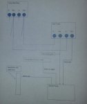
Wiring Diagram1.jpg

Robbie,

Not sure if the above image will come out big enough or not, but here is the basic idea. Add a jumper from each of the two output pins of the pump filter relay, and connect to the two input pins on the Aux 7 relay. Then wire your 220 volt pump to the two output pins of the Aux 7 relay. I suspect that the 220 Volt Stenner pump only has two hot leads and one ground, but added where the neutral (white) wire will go in case it is there.

The whole concept here is that you do not want the pump to run if the main pool pump is not running, so taking the 220 Volts from the Pump/Filter relay ensure that this can not happen. Then, but routing the power through the Aux 7 relay, you can control just how long you want the Stenner pump to run. If the picture does not come out, I'll try again.

Jim R.
 
  • Like
Reactions: Jerz
Hello, Were you able to finish the Stenner installation? I am curious because I have a Pentair EZ Touch 8 and would like to know how you wired it. How is this working for you?
 

Enjoying this content?

Support TFP with a donation.

Give Support
View attachment 39722

Robbie,

Not sure if the above image will come out big enough or not, but here is the basic idea. Add a jumper from each of the two output pins of the pump filter relay, and connect to the two input pins on the Aux 7 relay. Then wire your 220 volt pump to the two output pins of the Aux 7 relay. I suspect that the 220 Volt Stenner pump only has two hot leads and one ground, but added where the neutral (white) wire will go in case it is there.

The whole concept here is that you do not want the pump to run if the main pool pump is not running, so taking the 220 Volts from the Pump/Filter relay ensure that this can not happen. Then, but routing the power through the Aux 7 relay, you can control just how long you want the Stenner pump to run. If the picture does not come out, I'll try again.

Jim R.

Why does the diagram show a neutral connection. If 230 V is used, there is no neutral, just two blacks and a ground. If 120 V is used, it would be just one hot lead, neutral and a ground. The setup I use is a tap off of each of the two wires going to the pump, then through both poles of an AUX relay in my Easy Touch then to a dedicated 230 outlet near my Stenner. Ground is also supplied to the outlet.
 
I have Stenner 120V, what is the way to wire to the Intelitouch panel. I assume I cannot do like the diagram because of 120v. I have the same setup as robbief00.

Thanks
EL
 
I have Stenner 120V, what is the way to wire to the Intelitouch panel. I assume I cannot do like the diagram because of 120v. I have the same setup as robbief00. Thanks EL

EL,

You can use the same diagram but just not use the wire labeled as "Red or Black wire" and the corresponding wire between the Pump Filter Relay Out pin on the right and the Aux 7 relay In pin on the left.

The whole point here is that the Pump/Filter relay ensures the pump is on before applying power to the Aux 7 relay, which when energized applies power to the Stenner. Obviously you can use any Aux circuit, it does not have to be #7.

Jim R.
 
utell,

Sure you can put an outlet between the relay and Stenner, so that all you need to do is plug the Stenner into the outlet. You could add an external outlet to the side of the EasyTouch or inside the Easytouch if you wanted.

I'm not sure that it has to be fed from a GFCI source as the Stenner and water do not come into contact with one another, but I would do it anyway..

Jim R.
 
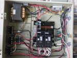
Thanks. I finally was getting around to install it. However, I forgot my Itellitouch was original an EasyTouch 4 and it looks like I am missing relays. Pentair replaced it right the build due to some issues. Attached is a picture of the inside of my unit.

So my question is:

Do I need to add a relay and then run that to an open AUX?

I assume I can grab power to add a new plug inside from the GFI breaker/outlet.

I am still confused about tying that new relay to when the pump is running.

Any help is appreciated it. I am pretty good at small electrical things; however, I want to be extra careful here.

Thanks,
Eric

IMG_5926.jpg

IMG_5927.jpg
 
Eric,

The relay in the upper right is your Pump/Filter relay. The white and yellow wires coming out of the relay already go to your 220 volt SWCG Transformer. This allows power to only go the SWCG when the pump is on.

Edit.. removed my original directions which were so wrong... Jim R.

(Since the Pump/Filter relay is already being used as a 220 volt source for your SWCG transformer, you will need to use a 220 volt Stenner)

Thanks,

Jim R.
 
Jim,

Thanks. I think I got it. I assume you meant upper left relay is the pump. Picture came out rotated negative 90.

One question is neutral bar. Do you mean the connected group of white wires?

Best,
Eric
 
Eric,

Why are you taking instructions from a guy who can't tell his left from his right!!! :p Yes, upper left on the panel...

(Edit) Removed the instructions for making an expensive GFCI tester... :(

You will need a 220 volt Stenner to make this work...

Jim R.
 

Enjoying this content?

Support TFP with a donation.

Give Support
Thread Status
Hello , This thread has been inactive for over 60 days. New postings here are unlikely to be seen or responded to by other members. For better visibility, consider Starting A New Thread.