
I'm in the process of replacing my ancient single speed pump with a new dual speed one (Pentaire Superflo Dual Speed 1 HP). I'm good on the plumbing side and I'm pretty comfortable on the electrical, but would appreciate feedback/confirmation that my understanding & plan is correct, or suggested corrections. Here's the scoop.
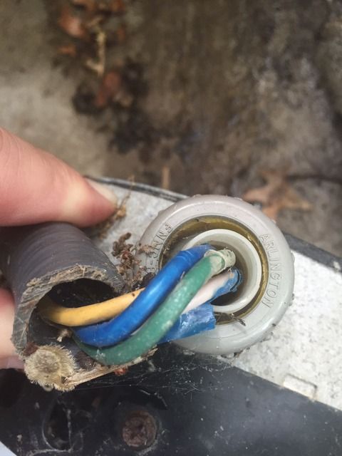
Both the old and the new pump are 230V, and the existing electrical to the pump looks like this: 4 lines - green, yellow and two blues, one of which has had the blue wrap removed to expose white casing, so I'll call it blue/white.
Schematic on the existing pump:
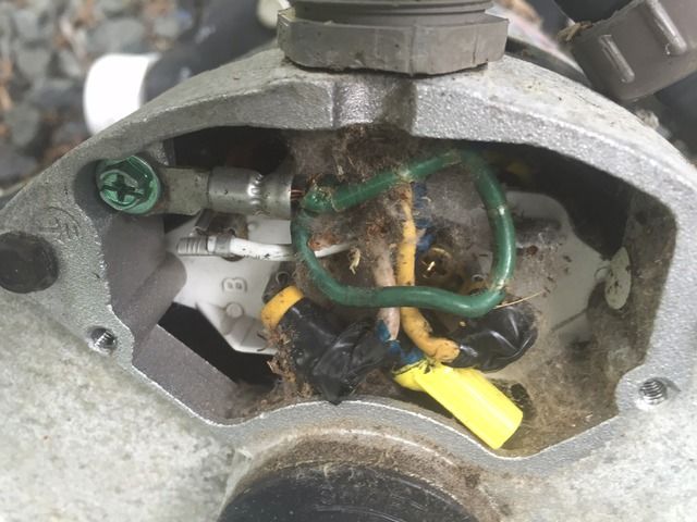
Pretty dirty inside, but here is the existing wiring: Green - ground, Yellow - A, Blue/white to B, and second blue not connected but just capped off with twist on connector.
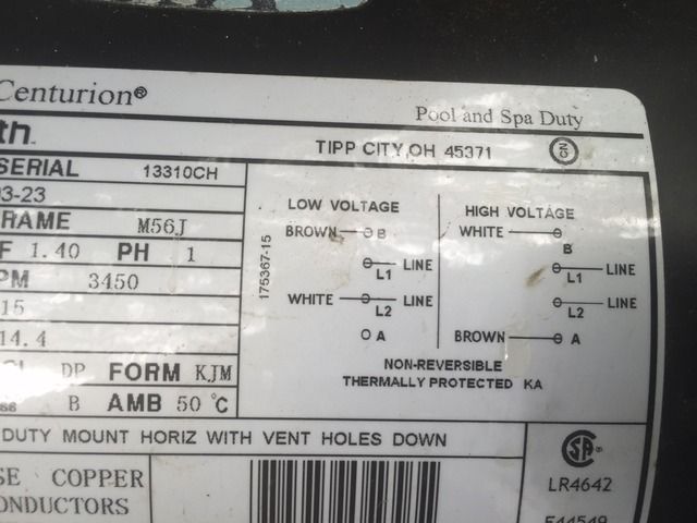
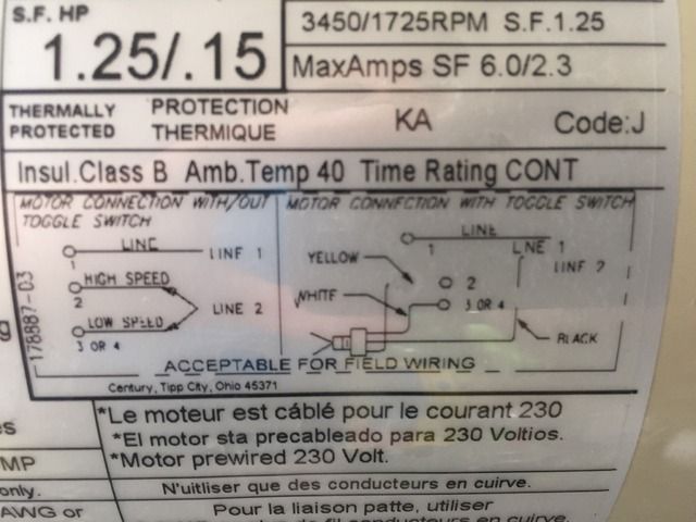
Now, moving on to the new pump. Following are shots of the new pump and schematic.
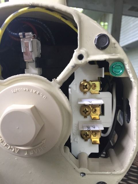
And the toggle switch:
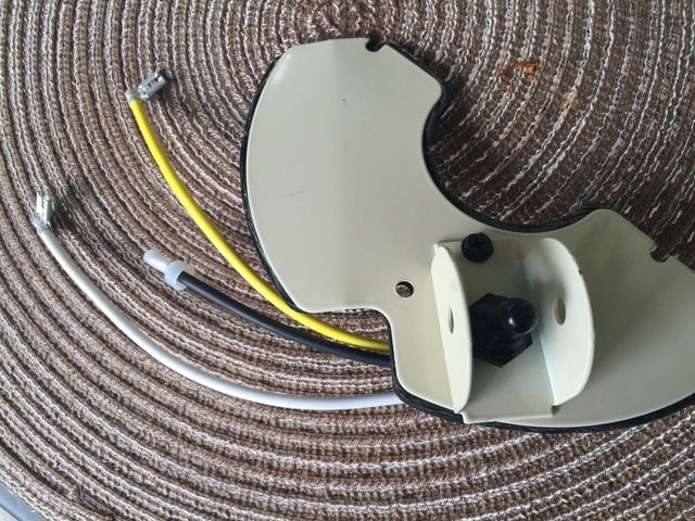
1. Obviously the green is the ground, but I'm looking for reassurance that for 230 the yellow connects to terminal 1, and the blue/white to the middle black line on the switch. Is this correct?
2. Is the 'extra' blue line there IF I wanted to wire it as 110V instead of 230V, but since I'm sticking with 230V it should continue to be unused/capped?
3. Switch wiring: The yellow on the switch to terminal 2, and the white to terminal 3 or 4; and as stated above, the black on the switch to blue/white line.
I hope I explained that clearly enough, but if not let me know and I'll try again!
Thanks very much for any feedback!
Both the old and the new pump are 230V, and the existing electrical to the pump looks like this: 4 lines - green, yellow and two blues, one of which has had the blue wrap removed to expose white casing, so I'll call it blue/white.
Schematic on the existing pump:
Pretty dirty inside, but here is the existing wiring: Green - ground, Yellow - A, Blue/white to B, and second blue not connected but just capped off with twist on connector.
Now, moving on to the new pump. Following are shots of the new pump and schematic.
And the toggle switch:
1. Obviously the green is the ground, but I'm looking for reassurance that for 230 the yellow connects to terminal 1, and the blue/white to the middle black line on the switch. Is this correct?
2. Is the 'extra' blue line there IF I wanted to wire it as 110V instead of 230V, but since I'm sticking with 230V it should continue to be unused/capped?
3. Switch wiring: The yellow on the switch to terminal 2, and the white to terminal 3 or 4; and as stated above, the black on the switch to blue/white line.
I hope I explained that clearly enough, but if not let me know and I'll try again!
Thanks very much for any feedback!