Wiring Timer and Chlorine Pump?

kmb997

0
Jun 13, 2007
111
New Orleans
I have an Intermatic timer (PF1103T) and a Stenner chlorine injection system. I would like to know how to wire these two together? I would like the pool pump and chlorine pump to be on at the same time, but I would also like to take the Stenner inside, during the winter. I would like to be able to do this by just unplugging the Stenner instead of opening the timer and changing wiring. Is this possible?

Thanks
 
Wire in an outlet in parallel with the pump on the load side of the timer(if you want the timer to control it,) and cover it with an "in use" weather proof cover. If you want to get fancy, you can put in a duplex outlet, remove the "hot" jumper tab, and wire one hot side to the timer line side and one to the load side, then you'll have one outlet controlled by the timer, and one that is on all of the time. That can come in handy if you want to run the stenner, and not the pump. The above assumes a 120V circuit with enough capacity for both the pump and the stenner. If its 220, than you can use one leg, but that can wreak havoc on a GFI. ALWAYS EXERCISE EXTREME CAUTION WITH ELECTRICITY!! A qualified electrician should easily be able to do that for you. Good Luck!!!
 
I hooked everything up and the timer is not turning the pumps off. I'll try to explain how it is hooked up and maybe you can see what I did wrong.

I connected the black to the black on the line side of the timer, the white to the white of the line side of the timer and to the white going to the outlet, and the ground to the ground screw. Then I connected the blue, of the load side, to the black going to an outlet. I capped the red and yellow lines off. When I change the setting, on the timer, from on to auto to off, the outlet still has power.

This is how the 120 volt wiring diagram described how to make the connections. Let me know what I did wrong or if something is wrong with timer?

Thanks
 
Here are some pics. The line side is coming from the breaker box and the load side is going to an outlet. I want the outlet to be controlled by the timer.

Thanks
 

Attachments

  • IMG_1515_3_1_1.JPG
    IMG_1515_3_1_1.JPG
    52.3 KB · Views: 202
  • IMG_1514_2_1_1.JPG
    IMG_1514_2_1_1.JPG
    77.5 KB · Views: 195
What have you gat the thermostat set to?

"Model PF1103T Freeze protection Control is self-contained in an indoor-outdoor, beige, rainproof enclosure and designed to automatically control as well as protect pool and spa equipment and plumbing against freeze damage. The control, if wired according to instructions, turns ON/OFF the Filter Pump on a daily schedule and also turn ON the Filter Pump when the air temperature (where this Control is located) drops below the temperature set by the thermostat dial (between 32 F and 45 F). Nevertheless, the control is not intended to be a substitute for insulation, covering or maintenance."

Verify that the timer-relay connections are correct
[attachment=0:3kfl3uo0]PF1103T-wiring-diagram.gif[/attachment:3kfl3uo0]
It looks to me like you have the wiring correct. Can you hear the internal relay click as you cycle from ON-OFF-AUTO?(Probably have to disconnect the load to hear it)
Good Luck! (More pictures are always Helpful!) :-D
 

Attachments

  • PF1103T-wiring-diagram.gif
    PF1103T-wiring-diagram.gif
    59.9 KB · Views: 188
Temp. is set at 32*. I didn't fool with the relay or t-stat because I thought it came ready to go. I will take a look at it and make sure everything is good. Yes, I do hear a click when switching from auto. to on and from auto. to off.

Thanks
 
The timer does appear to be wired correctly, assuming the bottom left hand wires are supply and the bottom right are load.

I believe you said that the pump stays on even when the timer is off? If so, the pump probably isn't wired to the load side of the timer. Does the outlet turn on and off? Perhaps a picture showing where the conduits coming into the timer come from?
 

Enjoying this content?

Support TFP with a donation.

Give Support
The wires on the bottom left come from another outlet that comes from the breaker box. I checked that earlier and it is wired black to black, white to white, and ground. Then it comes into the timer and is wired like the diagram shows. Then it goes out of the timer, bottom right, to an outlet that the circulation and stenner pumps plug into. The pumps stay on no matter what mode the timer is on. I tested with a voltmeter earlier and no matter what setting the timer is on, the blue wire is always hot. I'm pretty sure the blue wire should not have any voltage when the timer is off. This is possible for a timer to control an outlet, right?
 
Yes, it is totally possible for a timer to control an outlet! You appear to have it setup exactly right. It really doesn't look like you have done anything wrong.

If you are fairly comfortable with working with electrical stuff I have a test you could try. This is a little dangerous, don't attempt this unless you have experience working around live wires. Disconnect the blue to black wire nut on the output side of the timer. Then check the blue wire for voltage with the circuit live and the timer off. If the blue wire is live then there is something wrong with your timer. If the blue wire is dead then there is some other path for electricity to reach the outlet other than the timer.
 
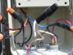
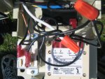
I can't tell from the pics if any of the wires are shorted together, but it's either that, or the internal timer relay is faulty, or the thermostat is shorted. I'm sure that you disconnected the thermostat to see if that was the problem. If you don't need the external relay (and the thermostat,) I'd bypass them. Here's how I'd check the timer and wire it-
0. TURN OFF POWER
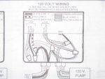
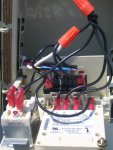
1. Remove all of the wires from the back of the timer.
2. Connect Neutral (White) to terminal 1 of timer, Hot(Black) to terminal 2.
3. Check the internal timer relay with an Ohm-meter, should be open (infinite) between terminals 3 and 5 and shorted(very low resistance) between 3 and 4.
4. Turn on power, timer should display time, check for voltage between terminals 1 and 3, 3 and 5 and 3 and 4.
5. Cycle timer ON-OFF, while watching for voltage changes between 3 and 4 and 3 and 5 (IF there was voltage present in step 4, if not check for resistance changes.
If the internal relay is working, then you will see voltage/resistance changes on terminals 3/4/5. if you don't, them the internal(Timer) relay is bad.
If the internal timer is OK, then TURN OFF POWER, connect neutral (White) from line and load to terminal 1, Hot(black) from line to terminals 2 and 3, and Hot(black) to load from terminal 4. Turn on the power, and enjoy!
Good Luck!
 
Thread Status
Hello , This thread has been inactive for over 60 days. New postings here are unlikely to be seen or responded to by other members. For better visibility, consider Starting A New Thread.