Hydraulics 101 - Have you lost your head?

mas985

TFP Expert
LifeTime Supporter
May 3, 2007
16,815
Pleasanton, CA
Pool Size
20000
Surface
Plaster
Chlorine
Salt Water Generator
SWG Type
Hayward Aqua Rite (T-15)
Edit - Before reading this article, you may want to first familiarize yourself with this Pool School article on Pump Basics

Hydraulics 101 - Hydraulics, Pipes and Filters

When building my pool, I did a significant amount of research on swimming pool plumbing and water hydraulics. I also found that there appeared to be a serious lack of understanding in the pool industry of exactly how pumps and plumbing interact. So I attempted to compile all of the information that I have gathered over the years and present it here. Most of what I learned about pumps and hydraulics comes from Joe Evans and his web site Pump Ed 101 and I encourage everyone to read his articles which are very informative.

Hydraulic Head

In fluid dynamics, head is a concept that relates the energy in an incompressible fluid to the height of an equivalent static column of that fluid. From Bernoulli's Principle, the total energy at a given point in a fluid is the energy associated with the movement of the fluid, plus energy from pressure in the fluid, plus energy from the height of the fluid relative to an arbitrary datum. Head is expressed in units of height such as meters or feet. - Wikipedia
Hydraulic Head is a term that originated in the water distribution industry and relates to the "head" or top of the water level. It is also another way of expressing the amount of pressure (PSI) lost or gained in a plumbing system. For example, a pool pump adds head or pressure to the plumbing system while the friction loss in piping and equipment removes head or decreases pressure in system. In addition, there are two basic types of head loss and gain in any plumbing system; Static Head and Dynamic Head.

Static head is the net elevation change of the water which can be either positive or negative and is directly related to the height of the water. So water moving from a higher elevation to a lower elevation has head gain while water moving from a lower elevation to a higher elevation has head loss. For example, in a pool solar system installed on a roof and where the panels/pipes are primed and completely filled with water, there is static head loss when the water rises to the roof but then there is also static head gain when the water falls back to the ground. The static head loss on the way up is directly offset by the static head gain on the way down so there is no net static head change due to the fact that the solar is installed on the roof. However, there can be temporary static head loss or gain during the priming process where there is head loss due to the elevation lift but since the return pipe is not yet full of water, there is no static head gain to offset it.

The second component of head is dynamic head loss which is due to the friction loss of water inside of pipes, fittings and other equipment. As water travels through a pipe, the friction against the internal structures reduces pressure. A pool's plumbing system will experience dynamic head loss on both the suction side of the pump and return side of the pump since water is moving through plumbing on both sides. The faster water moves through a pipe, the more head loss. A pool pump adds dynamic head gain to the plumbing system so as to create positive pressure and thus water flow through the pipes. The dynamic head loss in the pipes then reduces the pressure until the water returns to the pool where the pressure is once again at 0 PSI.

In summary, pumps and elevation drops add head to a plumbing system while elevation rises, pipes, fittings, valves, filter, heaters, etc. subtract head from a system. For a swimming pool, the total head loss is always equal to the pump's head gain since the water is returned to the same atmospheric pressure as where it came from.


Water Velocity

There are three reasons to be concerned about water velocity in plumbing:
  • High water velocity can result in high head loss.
  • High water velocity in suction lines and main drains can increase the risk of entrapment.
  • High water velocity can also increase the risk of hydraulic shock (water hammer) which can cause damage to plumbing weld joints.
To address these issues, you will sometimes see web sites quote recommended maximum flow rates in piping usually in the range of 5 ft/sec to 10 ft/sec for PVC piping. However, it is important to understand that these are only recommendations and not hard limits. In other words, if you can find a big enough pump, the flow rate can and will exceed these velocity recommendations. There is no fundamental limit to how fast water will travel in pipe.

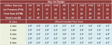
Increasing the pipe size in plumbing will usually result in lower head loss but there are diminishing returns because the pipe is only part of the total head loss. Filters, heaters, valves and return eyeballs all contribute to the total head loss of the plumbing. In general, it is a good idea to go with at least 2" plumbing in a pool system and ideally using 2.5" to add some efficiency. For spa jets which require high flow rates, 2.5" should be considered the minimum with 3" pipe providing better flow rates for the jets.

Issues of entrapment are addressed by the Virginia Graeme Baker Act and the ANSI/APSP-7 standard which state that for residential pools, the water velocity should not exceed 6 ft/sec in the piping within 3 feet of a suction port and 8 ft/sec in the line going back to the pool. This is easily accomplished with large piping which should be done to limit head loss anyway.

As for water hammer, high flow rates in plumbing have the potential to damage plumbing should a valve close suddenly. Repeated stress cycling of PVC pipe will eventually cause failures and the cycles to failure is directly dependent on the average pressure of the pipe and amplitude of surge pressure in the pipe. Several charts are shown in a Uni-Bell paper indicate that most failures occur at very high pressures or large cycle times. Fortunately, failures due to water hammer are fairly rare events in pool plumbing so there is not too much to worry about.


Pipe Sizing

Choosing the correct pipe size is very important for high efficiency plumbing. Ideally, it is best to keep suction pipe velocity below 6 ft/sec and return pipe velocity below 8 ft/sec. This helps prevent suction side issues such as entrapment and air leaks. Also, it is a good idea to have a separate suction line from each skimmer and/or main drain pair from the pool all the way to the pump so that one can isolate suction lines if necessary.

The water velocity in a pipe is determined by the size of the pipe and the flow rate going through the pipe. Below is a table of common pipe sizes and the recommended flow rates for three different velocity specifications.

y4m1k5YyVHLNVpNkBcNn24E1Kmafu8CYDUAMAjokwpKR3T04CtX3bLknyC5iXLfDqqhwE_WYvgSQQ0LjKlpxfiweq2BxD8Hhcn9Te6x3Z1FeG_WRDdFyQ4YzcvnwtqoVSTdzDsc7akTZR9RNJyFVGO6WxJzPG7XBT4OcLCzoi06BvGowskJfGfSrVgVi6u84-PwpZiQT6BZRXW0tU5d1Gl7eg


Another way to reduce water velocity in pipes while maintaining high flow rates is to use multiple parallel pipes. The table below shows the equivalent diameter of pipe for multiple pipes of another diameter and equal lengths. N is the number of pipes from 1 to 10 and across the top is the diameter of each pipe. The values within the table are the equivalent diameter for a single pipe.

y4m3W6r2EwOVqCyjNwTVqduqnuFls1iWsD0E4IE3EvfDvquwAmdSjiai4RBXJeOJIVZ8G2twy2u0O9eQw72YJQ2-u9zpqv8FryiYESpIENZyh9ArWiREbEg7pfOotPq6N62uR55mUvRAhIqijISF7Cvr7eV_iITPqYvFH3yEZ-msYr9eESpJJm2rhR7-78FuW2A3qOeFSYtPp9hPDRBcCrbRg


Filter Sizing

There are three basic types of pool filters each with pros and cons; Cartridge, Sand and DE. Which filter is best for you depends on several factors:
  • Cartridge Filters: Most energy efficient and don't require back-washing. Best suited for areas with water restriction, high electrical rates and/or pools that use a SWG.
  • Sand Filters: Easiest for algae clean up. Best suited for areas where the pool is closed for the winter and/or high algae potential.
  • DE Filters: Best filtration. Best suited for owners that really want their water to be as clean as possible.
As for sizing the filter, the following table is derived from the APSP-15 and ANSI/NSF 50 Specifications and shows the minimum recommended filter size based upon the specifications maximum GPM/Sq-Ft for each filter type. These requirements are shown in the APSP-15 standard and are now being adopted as regulations by many states for both public and residential pools.

y4mHqdQOG6r4Lx6FkAv8Sbqw5eGOjz_6S_iZK8ePH0cUaFu9vf5UwgRd3rWddPcUzXCnlvp-d0QNsR1uv2e5cqNoaz5MmWFObDIZHlv7c1ic48Z5Ugp7rAlCxzzk3higFvjnnb9g-TMonaZu4FuHe8pNN3-DADfGFnVgov8bnP7RZ7-El9jSHIu-SEOIx6YzGzzB27jO6uX4bwkm82WjIo1FA


In some cases, the minimum filter size will be dictated by the pump maximum flow rate rather than the pool size so BOTH must be taken into account. The filter sizes are determined from a 6 hour turnover so even if an 8 hour turnover is targeted, the filter sizes would still be appropriate and have an extra 25% margin. Also, for cartridge and DE filters, increasing the size of the filter beyond what is shown in the table is generally a good idea and will minimize the number of cleanings per season and minimize cleaning damage.


Filter Head Loss

One thing to consider when choosing a filter is that filter head loss can vary by quite a bit depending on the type and size of the filter. In general, a cartridge filter will have the lowest head loss of any filter mainly because they typically lack a backwash valve which can add quite a bit of head loss. In addition, small sand filters can be high in head loss because of the smaller media surface area. Below is a table of different filter configurations with their associated head loss.

y4mw9A5fKuq9dktlWdNU999fFrMqVMgBBmdTuYz8cqBGB-SinrHhUCGpZVt0zTApoNaTatslPk33bkWCewGL0DUUv9f8j1kKqhckb52onj33YN-x_fkYgXL5GyUWZbmgMfdp04G_0Ox8GLJYY-E3xzp3J2PBdqhDP_k1GOJ2BkEUws_fMnCrWhe9ntpAp69ozVSiPu6DlEGP58z7lMB3R4zmg


Check Valves

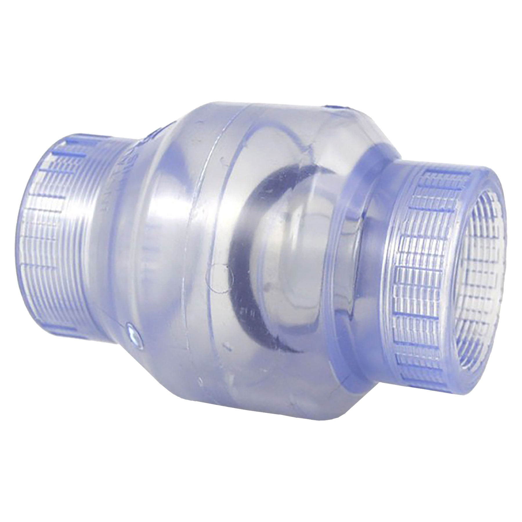
Choosing the wrong check valve for your system can have a drastic effects. Try to avoid the hardware store variety check valve that use a large spring loaded plug. This type of check valve has very large head loss and can create major problems for solar installations as well as for general use. This type of check valve usually looks like This:

y4ma8xn0yo-uXCpGbUP6L3eGuT6baTOeWZE7_xE8C-NvwbH9QNC3IGoh0LTsVySOq4gEn1QKZFvjNlNNgSzsJyBefGbdlYS2NhIqZ-Vzl2Dvrj3YZI1Qey-nyEE869y-NzgD2qDHF3LTKCPNhEpwnzzeQ_DkbDOf2iqjWuiH1Mc93mgmPZKWjLoJkNs0Hrc_YC-Zv9PtiV_A87_6mxPhGx8eg


A better type of check valve uses a flapper mechanism instead of a large spring. This type of check valve looks like this:
Spears-Swing-Check-Valve-Threaded_fa0629fb-78f3-4fd4-b537-bca6e73c5d0d.jpg


The best type of check valve and one with the lowest head loss is made by Jandy and looks like this:

y4mCzR5Nv5RGOmnxvg8ouDBLn3mJTE0_KT3s1-sX14aHomVajv2bntmecuaKCYqYrSE0jDzyJQIW41EOz0kl-_a3wFP_awIzseyyFtPgSr6wdXYcHZPMQO9ka0L3PWI1M7Php6NzvuWY9h9Bhh_PgenwTukudzs2SYzMy9eFIe0bmjP_lkqJuded763SeM5YIkrXGWOIhs-yLUXtAYA4CaHEQ
 
Last edited:
Hydraulics 101 - Pumps

Pool Pumps


A residential pool pump is actually made up of two separate "machines". The first machine is often called the "wet end" and this is the part that actually pumps the water and converts rotational energy into flow and pressure. The second machine is the electric motor which converts electrical energy into rotational energy and drives the wet end. Together, these two machines make up a residential pool pump and this section will help you understand the contribution each makes to the over all efficiency of a pump.


Pump Head Curves

Most manufactures of pumps include head curves in their pump manuals. The curves have two axes, Feet of Head vs. Gallons per Minute (GPM). Feet of head is used instead of PSI because a centrifugal pump will always deliver the same head for any liquid while the PSI will be different for different liquids so traditionally, manufactures have used head instead of PSI.

The head curve is useful in determining the flow rate of the pump if the head loss of the plumbing system is known. Below is an example of a head curve for the Pentair Intelliflo.

y4mbN1vuLK7DOgZ68thMAXNTyvWKOd9ve40Rqit5LsY7PXw4a2QLXLDKuwXOXNqnoLPbrDhJriaXIhzT-IoBJ9lG2J2IQhT5Dr3Unhbkem3qmr_SCivoODAjy4cVErbJiH93rAIP03UJ4ndpYSrKxJXMjKxUb_nyYB0Yo4GZsY7fMcfYLZNiXZw31_J3vjBvk_-qjsmADI-dOpHcQPJpoEj7w


The maximum head of the pump is reached when the flow rate is near zero GPM and at full RPM. This is equivalent to an equal length of open ended pipe straight up in the air. The pump will fill the pipe to the top but no water will spill out.

This particular chart also shows that the energy use of a pump is fairly linear with the flow rate. This is true for all residential pool pumps. The higher the flow rate of the pump, the more energy that is used. However, flow rates tend to increase faster than the energy use which is why the energy factor of the pump as measured as gallons per Watt-hr, increases with increasing flow rate effectively reducing the energy consumption. However, there is a flow rate limit that a pump can produce which is called run out but most pool installations will never reach this limit because there is always at least some plumbing head loss.


Pump Motor Nameplate (pre 7/19/2021)

Most in the industry have long understood that pump motor nameplates can be very deceiving which often leads to incorrect sizing. It is bad enough that manufactures have chosen to have two classes of IG pumps, up rated vs full rated, but AG pumps also come in an "Special HP" (SPL) version which is basically a double up rated pump.

So what do all these terms mean?

The horsepower required to turn an impeller at a specific RPM is called brake HP (BHP). The required BHP changes along a pump's head curve and reaches a maximum near the right side of the curve. A motor will typically be rated at a service factor HP (SFHP) or total HP (THP) which is greater than the maximum BHP required for the pump. The SFHP/THP is the true measure of a motors power capability and is determined by multiplying the pump's service factor by the label HP. This is where a lot of the confusion originates. As a general rule of thumb, here is how a pump's service factor relate to the ratings:
  • Full Rated: Service Factor > 1.3
  • Up/Max Rated: 1.0 < Service Factor < 1.3
  • SPL Rated: Service Factor < 1.0
Within the same pump line, sometimes you will see two pumps with different label HP and service factors but identical head curves and identical THP (service factor * label HP). Don't be fooled by this, if the head curves are the same, the pumps are identical. Only the labels are different. So the lesson here is that you cannot judge a pump's power or strength just by just the nameplate HP rating.

To illustrate this point, the chart below shows the flow rates of several Pentair and Hayward low HP IG and AG pool pumps using two of the CEC plumbing curves, Curve-A and Curve-C. The higher the flow rate, the more powerful the pump.

y4mw8o0xawXWLej4KGS--AAU7KaVaOWn1lTzKKRmtFnh1PdR4C8blfvjIe2STaUlmG5PNYb2pMqNckc9gVZTtf3gLPe64ZEnt0QWv-co7G5GOxIKlsCFrfqXsYypTdPOVlylV87kUtJcF4o9pUgPu58IZPQx43WDLNAlvxlwIanub6dvQC8NuUKXl7Q5871KtkemTu2zBwOahgPiDV2oHhQzQ


Even when comparing IG up rated pumps, there is clearly a large difference between the Whisperflo and Superflo line of pumps that have the same nameplate HP. But the difference is just as great when comparing IG to AG pool pumps with the same nameplate HP. Both the Optiflo and Dynamo are significantly smaller than even the Superflo with the same nameplate HP rating. Below is a list of terms that one should be familiar with when choosing a pool pump.


Motor Nameplate Definitions (pre 7/19/2021)
  • Nameplate HP (NPHP) - This is the HP rating on the motor nameplate but is pretty much meaningless without the service factor.
  • Full Rated HP (FRHP) - Similar to nameplate HP and sometimes used when the pump is full rated.
  • Up Rated HP (URHP) - Similar to nameplate HP and sometimes used when the pump is max rated or up rated.
  • Nameplate KW = NPHP * 0.7457 - This is the KW rating and is similar to the nameplate HP and is generally used outside the US. Note that this is not the input power to the motor only the rating for the output power of the motor.
  • Service Factor - This is an overload rating for motors which states that the motor can be safely operated over the NPHP by the service factor for short periods of time. However, for pumps, this overload rating is typically used as the maximum load that a motor would need to deliver to the wet end. Because the load on a pump does not rapidly change over time, the service factor load is often used as the maximum design point for the pump.
  • Total HP (THP) or Service Factor HP (SFHP) = NPHP * Service Factor. This is the maximum load that can be safely driven by the motor and must always be greater than the maximum load from the impeller. A motor can be driven above the THP but will likely fail in a short period of time.
  • Electrical Horsepower (EHP) = Input Watts / 745.7 = Volts * Amps * Power Factor / 745.7 - Electrical power input delivered to the motor.
  • Brake Horsepower (BHP) = EHP * Motor Efficiency - Power delivered by the motor shaft to the impeller. This is not the same as THP or SFHP. BHP is a function of the load on the motor shaft and will change with Head, GPM and RPM.
  • Hydraulic HP (HHP) = BHP * Pumping Efficiency = Head (ft) * GPM / 3960 - Power delivered to the water. Sometimes called water HP (WHP) or pumping HP (PHP).
  • Motor Power Efficiency = BHP / EHP - I2R, magnetic and mechanical losses in the motor only.
  • Pumping Power Efficiency = HHP / BHP - Recirculation and internal friction losses in the wet end only.
  • Total Pump Power Efficiency = Motor Efficiency * Pumping Efficiency = HHP / EHP (note this is why total pump efficiency approaches 50%).
  • Energy Factor - Gallons/watt-hr = GPM * 60 / Watt-hr; A CEC definition used to quantify a pump's efficiency.
  • Service Factor Amps - The amp draw when the motor is loaded to the service factor. Also, multiplying the SF amps by voltage should also give a good estimate as to the upper limit for power draw. However, sometimes the motor is over dimensioned for the pump so it will not always be an accurate measure of input power. NEMA tolerance for this parameter is ±10%.
  • Full Load Amps - This can mean several things depending on the motor manufacture. It is either the amps at the NPHP or it can be the amps at the THP. I have seen it both ways so unfortunately, there is not a good standard for this one. NEMA tolerance for this parameter is ± 10%.

Pump Speed

Typically, a single speed pump will operate at around 3450 RPM. But there can be significant advantages when running at lower RPM. The pump affinity equations can be used to determine how a pump's characteristics will change with speed. So if the flow rate, head or hydraulic HP is known for any one speed A, it can be calculated for another speed B using the following formulas.
  • GPM B = GPM A * (RPM B / RPM A)
  • Head B = Head A * (RPM B / RPM A) ^ 2
  • Hydraulic HP B = Hydraulic HP A * (RPM B / RPM A) ^ 3
But what do these equations really tell us? For one thing, a reduction in speed has a proportional reduction in flow rate but has a much more significant reduction in the required HP required to generate that flow rate. This is the primary reason a two speed or variable speed pump can save so much energy at lower speeds.

For example, low speed of a two speed pump has about 1/2 the flow rate as high speed and the affinity equations tell us that it requires only 1/8th the power of high speed. Unfortunately, two speed motors lose about half their efficiency at low speed so the energy use is only about 1/4th of high speed but still significant.

Current generation variable speed pumps provide even more cost savings over their two speed counterparts. Plus, given the range in RPM settings, the pump can be optimized for the given pool plumbing. The flexibility of a variable speed pump ensures a maximum energy factor for nearly any operating condition. Plus, current DOE regulations pretty much dictate the use of VS pumps now. Larger single speed and two speed pumps can no longer be manufactured in the US.


Pump Sizing

To conserve energy, the smallest pump possible is desired because it will use less energy than a larger pump. However, some pool features may require larger pumps than others:
  • Spa jets usually require 10-25 GPM per jet and and with many jets can require very high flow rates.
  • Water features such as waterfalls usually require high flow rates for impressive action.
  • In floor cleaners require fairly high flow rates and high pressure per head to provide enough power for cleaning.
  • Suction side and pressure side cleaners often require high head pumps but depending on the cleaner, can sometimes run on smaller pumps.
Even if one of the above conditions apply, the best of both worlds may be a two speed or variable speed pump. High speed can be used when needed and low when it is not. Operating this way will save energy and money.

Other considerations that are very important when choosing a pump are:
  • Above ground vs in ground pumps. They are generally not interchangeable so stick with the pump made for your type of pool.
  • Maximum GPM rating for filter size. Exceeding the flow rate specification for the filter may damage it.
  • Minimum GPM rating for heater. Most heaters require at least 30-40 GPM or the flow switch may prevent it from starting. This usually only happens for the low speed of a very low HP pump so if you want to use the heater on low speed, double the minimum flow rate to determine the high speed flow rate as minimum.
When designing a new pool, it best to first determine the maximum flow rate required for all of the features and then size the pipe and pump to that flow rate requirement. This will ensure the most energy efficient design for the requirements of the pool.


Spa Pump Sizing

The first step in designing a spa is to settle on the number of jets, size of jet and how strong you would like the jet to feel. Once this is determined, the following table can be used to determine the proper pipe size and the resulting operating point for the pump.

1702308237967.png

Note that for designs requiring more jets than a pipe or pump can support, multiple plumbing loops with multiple pumps can be used to achieve the necessary flow rates.

Solar Panel Considerations

If the solar panels are on the ground, most any pump can handle the extra dynamic head. However, when placed on a second story roof, a pump must overcome the initial static head of the panel's height during the priming phase of the panels. After the panels are primed, the static head going up to the roof is offset by the static head dropping from the roof when the return pipe is completely filled with water.

In order to ensure proper priming of the solar panels and the closing of the vacuum release valve at the top of the panel, the pump's head loss at 40 GPM should be twice the height of the panels. For example, if the peak height of a panel is 25 feet, then the pump should handle a minimum of 50 feet of head @ 40 GPM. Most full speed pumps will handle this fairly easily.

However, most two speed pumps at low speed will not have sufficient power to prime panels on a high roof since the maximum head at low speed is usually below 25 feet. The water may reach the top of the panel but there will not be enough pressure to close the vacuum release valve. If the valve does not close, then the static head loss will remain, total head loss will be high and flow rates will be very low.

In addition, even when the panels are primed and the pump is switched to low speed, there may not be enough pressure at the top of the panels to ensure that the vacuum release valve stays closed. So it may not be possible to run solar on low speed of a two speed pump. It may be possible for panels on a single story house but probably unlikely for a two story house.


Pump Cavitation

First, let's be clear, cavitation is NOT indicated by the presence of air in a pump basket. That is caused by an air leak in the suction side of the plumbing. Cavitation cannot usually be directly observed because it occurs at the impeller inlet which is blocked from view.

Cavitation occurs when the water pressure drops below the vapor pressure and the water boils. However, these vapor bubbles do not exist for very long and as they travel through the impeller, the pressure rises and the bubbles rapidly collapse causing a very distinct sound much like small pebbles traveling through the pump. It is the collapse of the vapor bubbles which can cause impeller damage.

Fortunately, cavitation is pretty rare in pool pumps and occurs mostly in larger high head pumps under very high suction conditions.


Pump WEF Rating

The Department of Energy has adopted a metric for rating pumps for their relative efficiency called the Weight Efficient Factor (WEF) and unfortunately, it is not the best way to compare pumps. The reason is in the method of WEF calculation. First, the definition of energy factor:

Energy Factor = GPM * 60 / Watts

For single speed pumps, this is a not the worst way to compare pumps (e.g. THP is worse) but when comparing pumps that can operate at multiple speeds, the speed at which you compare the pumps can give wildly different results. This is why WEF was created but there is a fundamental flaw in the methodology. For a VS pump, EF can be calculated at any RPM and the lower the RPM, the higher the EF down to about 800 RPM and then it will start to climb again due to the drive electronics overhead energy use. So the lowest EF is at full speed which plays into the WEF calculation.

In order to calculate WEF of a VS pump, two measurements are combined with a weighting factor for each. One measurement is performed at 80% of full speed with a 20% weight while the second measurement is performed at a lower speed with a specific flow rate (e.g. 31.1 GPM for HHP > 0.75) and a 80% weight. So what this does in effect is to lower the WEF for the larger THP VS pumps when in fact the larger THP VS pump in a particular pump line may actually have better efficiency at a given flow rate than the lower THP VS pump. So the best way to choose a VS pump is to pick the largest THP pump in the product line of your favorite manufacture or compatible with your controller. Then when operating the pump, choose the lowest RPM for the given task and you will be operating efficiently.


Pump Efficiency Comparison

So if WEF is not a good metric to use, how should pumps be compared. In short, pump energy use should always be compared at the same flow rate. But his is not always easy to do as some of the pump databases do not show energy use at specific flow rates.

Much like a pump, a plumbing system also has a head curve which is sometimes identified as a "Plumbing Curve". And much like a pump's head curve, the plumbing curve is parabolic in shape and when plotted over a pump's head curve, crosses the pump's head curve at a single point. This point is called the operating point of the pump/plumbing system. The plumbing curve of any plumbing system may be approximated by this simple formula:

Head (ft) = k * GPM^2

Where k is the plumbing curve constant that is dependent on the configuration of the plumbing system. The three plumbing curves included in the databases are defined as:
  • Curve-A which represents fairly restrictive plumbing typical of an AG pool or an IG pool with 1.5" pipe size. k = 0.0167
  • Curve-B which represents extremely high head loss conditions. Not many pools would fall in this category. k = 0.05
  • Curve-C which represents less restrictive plumbing typical of pools using 2" pipe size. k = 0.0082
The pump tools spreadsheet makes use of this concept to compare pump energy use at specific flow rate conditions. Note that these definitions of plumbing curve vs pipe size differs from that you may see from APSP or others. This because the APSP definitions are much more pessimistic that what is seen from of actual plumbing systems. The definitions shown here are based upon actual plumbing system averages from the forum.

The table below shows an example of an energy use comparison for several variable and two speed pumps. This spreadsheet is available for download here.

y4mCKIAqt-hsysz1_RKC9cp87q6gJPwJTELv1VMAL_xpQOKL_dL8ZqJchfMDdqNNgLdp23d5UGWloE0UJTjgeZkpqBEjaMXsnzJ2MyF8jhRD2mIB_mpl5Y9tWRuDcpHYYV38GO9x7uF4GkRpbotFauvSlBPNZAYXauf8D6Fzx1LCvevF_jKvUEBvRjda5N_ejkco-xe21Kr9_3sjo04Fjws6g


Additional Reading
 

Attachments

  • 1702308020079.png
    1702308020079.png
    6.3 KB · Views: 9
Last edited:
  • Like
Reactions: Alitkh
Hydraulics 101 - Pump and Pool Spreadsheet Tools

Disclaimer


These spreadsheets are provided as is without any guarantees or warranty.

License Agreement

To get access to these spreadsheets, you must agree to the following license agreement:

  • These spreadsheets are for personal use only and shall not be used for any commercial business without the author's permission.
  • These spreadsheets shall not be copied in whole or part into another spreadsheet or application without the author's permission.
  • These spreadsheets shall not be sold nor distributed in anyway other than through this website.

The following spreadsheets are available here:
  • Pool Pump Tools - Estimates pump operating points, pump energy costs and waterfall flow rates. Now Macro Free and Google Sheet Version!
  • Pool Heat Transfer Tools - Estimates heat loss and gain from a full heat transfer model that includes the effects of the sun, solar panels, NG heater, heat pump, and environmental conditions. It will also estimate the amount of water lost per day/week due to evaporation. Included are tabs to estimate heat loss from pipes and how long it can take for a pipe to freeze. Now Macro Free and Google Sheet Version!
  • Chemistry Calculator - Calculate chemicals required to balance pool chemistry and logs test results.
For questions regarding these spreadsheets, please PM me.

Hydraulics 101 - Other Information

Plumbing Threads


DIY Threads


Other Threads

Reference
Motor Mastery University
Motor Doctor
Baldor Cowern Papers
PumpEd 101
 
Last edited:
  • Like
Reactions: CoolInDaPool
Hydraulics 101 - Troubleshooting

Air in the pump basket and/or lower than normal filter PSI:
  • Pump lid not sealing properly
  • Suction valves may be set improperly or partially off
  • Blockage in the suction side piping or valves
  • Clogged impeller
  • Undersized suction side pipe
Higher than normal filter PSI:
  • Dirty Filter
  • Return valves may be set improperly or partially off
  • Check for return side blockage
  • Over-sized pump
  • Undersized filter
  • Undersized return side pipe

Pump motor will not start:
  • Shaft turns manually but motor hums and will not turn - Bad start capacitor, replace capacitor
  • Shaft is frozen and motor trips breaker - Frozen motor bearings, replace motor
 
Last edited:
  • Like
Reactions: LiveHereNow
Thanks for all the info, Mark.

I've been wanting to calculate my pump/pipe needs, but haven't, primarily due to not having all the resources in one place. At least you have all the instructions to determine it in one place.

Based on your basics, and another thread that you just posted (on pvc velocity issues), I'm thinking that 2.5" suctions lines and 2" discharge lines will work good. I'll figure it out based on your info, and post for your review.

I'm in the middle of a build, and spec'd out 2.5" and 2" pipe, and my builder agreed. Not surprisingly, evidently he forgot to mention this to his plumbing guys of the day... so as we speak my pool is plumbed with 2" and 1.5" pipe. If he would've maintained some pace at all, I was going to let it slide, and force some compensation later... but now I've pretty much decided that I'm going to have him re-do it. My preliminary calcs indicate too much of a difference to overlook... and he's going to be slow, he might as well slow and right.

Thanks again for your work. Our world needs people like you... to help the non-focussed ones like me.
 
Much like the book burnings and witch hunts of times past, I think we should consider banning Mas985 for being too smart, too thorough, too practical and well, you know, all that other stuff.

I gotta run.......Jerry Springer reruns are on and I never miss an episode. :roll: :roll:
 
  • Like
Reactions: CSE1965
Hi Mark and Anyone else who might care,

I'm back. And as you state in your post above, calculating the head loss on a future pool is nearly impossible... especially when the estimator..... ain't too smart.

So in my quest to determine if its important enough to make my PB re-do the pipes that we agreed on, I did the following rough calculations, and it seems to be a fairly large difference... I'll let y'all comment on my calcs, and if the difference seems significant or not.

Background: I specifed 2.5" suction (drain) lines, and 2" return lines. (This seemed to be 1/2" larger than his "normal", but he agreed... no problem... and certainly put $$ to do so.) Weeks ago they did the plumbing, and haven't done anything since. I was going to "overlook" it, point it out later, and get some $ back one way or another. Now, since he's still dragging his feet, I'm thinking I might as well make him do it right (and slow), rather than wrong (and slow.)

I think the difference in JUST the RETURN lines justify re-doing all of it. My calcs don't even include the suction lines, although I'll have him re-do those also.

Spa return: 2" 60' long
Pool return: 2" 60' long
Total return length: 240 feet

Head loss due to friction, schedule 40 PVC pipe (http://www.plumbingsupply.com/pluminfo.html)
2" pipe 35 gpm: 2.21 feet per 100'
2.5" pipe 35 gpm: 1.66 feet per 100'

2" pipe 50 gpm: 2.4 feet per 100'
2.5" pipe 50 gpm: .88 feet per 100'

50 gpm: 2" pipe: 4.17 feetloss x 2.4 = 10.008 feet loss in my return lines (due to pipe only)
50 gpm: 2.5" pipe: 1.66 feet loss x 2.4 = 3.984 feet loss in my return lines (due to pipe only)

35 gpm: 2" pipe: 2.21 feet loss x 2.4 = 5.30 feet loss in my return lines (due to pipe only)
35 gpm: 2.5" pipe: .88 feet x 2.4 = 2.11 feet loss in my return lines (due to pipe only)

Ok… so how do you convert FEET to PSI… and is that a big enough difference to care about?

I will be using the Pentair 4x160, so I should be able to adjust it to pretty much what I need, assuming I can figure that out one day. My best guess is that pool will be about 24,000 gallons. Pretty odd shaped. Hard for me to calculate.

Thoughts??
 
First,

Filter PSI = Return Head Loss / 2.31

But the pipe is not the only contributor to head loss. The fittings and rest of the equipment actually add much more than the pipe runs.

I happen to have an Intelliflo model and for a typical pool with 60' runs, here is what you can expect


RPM 3450 2500 2000 1000
2.5"/2.0" Head Loss 74 39 25 7
2.5"/2.0" GPM 104 74 59 28
2.5"/2.0" Filter PSI 25.2 13.4 8.6 2.2

2.0"/1.5" Head Loss 87 46 29 7
2.0"/1.5" GPM 72 51 40 19
2.0"/1.5" Filter PSI 30.2 16.0 10.3 2.6

Sorry about the fomatting. Hopefully you can read it.

Now this is just an estimate but it gives you a feel to what it might be.

However, you may have an option which would not require removing what he already has laid. Have him add at least one additional line for the suction and return. So for the suction, have one 2" line for the main drain and each skimmer. Have at least two lines for the return and have him split them into two sets of eyeballs. How many skimmers and return eyeballs were you planning?
 

Enjoying this content?

Support TFP with a donation.

Give Support
Thanks again, Mark.

Here's the pipe (and how it's labeled) at the equipment pad:

MD Pool 2"
Skimmer 2"
Skimmer 2"
MD Spa 2"
MD Spa 2"

Pool Return 2"
Spa Return 2"
Spa Return 2"
Spa Jet 2"
Air 2"

Polaris 1.5"

Here's what I see in the pool:
(2) Main Drains
(2) Skimmers
(3) Returns
(1) Autofill
(1) Polaris?

SPA
(6) Jets?
(2) Returns?
(2) Drains

Thanks for the comment on the other equipment causing head loss. The only thing i have to hang my hat on in the contraact is the "pipe size." Not even the number of suction/returns is specified (my fault), therefore, the other equipment I have to assume is the same, for either pipe size.

If you think that adding a suction and/or return would be just as beneficial, I can certainly give him that option, if he'd prefer to do that than replace existing pipe. For what its worth, the pipe is laid, but there is no concrete over it.

Also, maybe worth mentioning, my spa has a relatively large spillover (about 5 feet wide.)

Thanks,
Steve
 
It's a little hard to tell how he is planning to plumb everything but this is what I think he is trying to do. It may be a good idea to get confirmation from him. See bold inserts:

stevenbrla said:
Thanks again, Mark.

Here's the pipe (and how it's labeled) at the equipment pad:

MD Pool 2"
Skimmer 2"
Skimmer 2"
MD Spa 2"
MD Spa 2"

If these are separte lines from the pool to pad, then this is fine. It looks like there is a separate line for the main drains and each skimmer. Again, smaller parallel lines can be just as good as a single large line.

Two lines for the SPA main drain. One is probably for the jets and another for circulation or they may be plumbed in parallel which is even better. It would be good to get a schematic from the PB to make sure of what he is planning here.


Pool Return 2"
Spa Return 2"
Spa Return 2"
Spa Jet 2"
Air 2"

Polaris 1.5"

It looks like he has one 2" line for the return which is probably ok. I am not sure why he has two lines for the spa return and only one for the jets. It could be for the large spillover which would make sense but spa jets like a lot flow too. It might be good to get clarity on that. You are planning for only one pump, correct?


Here's what I see in the pool:
(2) Main Drains
(2) Skimmers
(3) Returns
(1) Autofill
(1) Polaris?

SPA
(6) Jets?
(2) Returns?
(2) Drains

Thanks for the comment on the other equipment causing head loss. The only thing i have to hang my hat on in the contraact is the "pipe size." Not even the number of suction/returns is specified (my fault), therefore, the other equipment I have to assume is the same, for either pipe size.

If you think that adding a suction and/or return would be just as beneficial, I can certainly give him that option, if he'd prefer to do that than replace existing pipe. For what its worth, the pipe is laid, but there is no concrete over it.

You may have enough lines already. It sounds as though you have 3 suction lines and 1 return lines all 2" for the pool which should adequate. The spa is a little less clear on how he plans on plumbing everything together. For 6 Jets, 2" line is ok depending on the type of jet he will be using. It might be a good idea to check the recommended flow rate for the jets he will be using. 2" pipe is probably ok for 15 GPM/jet or less. The Intelliflo has more the enough power to overcome fairly high head loss but it is good to check anyway.


Also, maybe worth mentioning, my spa has a relatively large spillover (about 5 feet wide.)

Thanks,
Steve

In general, I think he is on the right track but without seeing the schematic, I cannot say for sure.
 
Thank for your thoughtful reply, Mark.

Getting a schematic from the PB might be possible. That's a BIG might. I wonder how much he really knows about anything, and I certainly wonder about how much he knows is actually going on at any particular build. His regular plumber didn't run these lines.. his dig crew (who seemed very pretty knowledgable) ran the plumbing... I think they had some free time that day. The plumber showed up the next to pressure test, looked it over, didn't say too much, got interrupted by rain, and hasn't been back since.

Now that I think about it, he did seem to know a little about it, because when I mentioned that they didn't run the deck jet lines, he said "I wasn't told about any deck jets." So he may have drawn up what they laid.

So adding to above piping, there will be 2 deck jets. We will have an extra pump to run either the deck jets or the spa... I'm not sure of the exact plan there. Again, plumber didnt know about the deck jets when he "designed" the system.

Nothing like have an absentee PB who keeps the design a secret.

The spa jets are Waterway Poly Storm Gunite Jete (210-3710). It looks like the heads available for it demand 10-12 gpm each.

I appreciate your comment that this should work. What are thoughts about how much it may cost me in the future in energy due to his decicion to use 2" returns rather than the 2.5" we agreed upon?

Thanks again for your help.

Steve
 
stevenbrla said:
...What are thoughts about how much it may cost me in the future in energy due to his decicion to use 2" returns rather than the 2.5" we agreed upon?

There are so many variables involved that I don't think it's likely anyone could come up with a truly accurate figure. If you run the pump "x" hours per day, any restriction in the return lines will actually reduce your operating cost (but at the same time reduce the number of gallons pumped). Are you installing a flow meter? If not, how were you going to decide how long to run the pump? My guess is that the real difference will be pretty small, bordering on neglible.
 
stevenbrla said:
I appreciate your comment that this should work. What are thoughts about how much it may cost me in the future in energy due to his decicion to use 2" returns rather than the 2.5" we agreed upon?

If you run at the lower speeds, it will have little impact and even at full speed, the turnover time will only be about 10% more.
 
Awesome thread, have a thought to sum things up for existing equipment owners who want to know minimum HP needs if they are wanting to make a change or go for a more efficient unit. If you are new to the basics, the cliff notes and one realworld example:

On your existing equipment you can find out your head loss by using a pressure gauge on the pressure side (a port on sand filters is already there).

Read the value and multiply by 2.31 to get the feet of head. Then add roughly 5 for the suction side loss....This will get you the head loss (which most struggle with) and from there you can use the manufacturers chart to figure out what HP system you need for the number of turns you are trying to acheive per day (usually 1-3).

My Pool as an example:

21000gal pool
3 turns a day this equals 21000x3 = 63,000gallons pumped per day
63000 gallons / (60x24) = 43.75 gallons needed per minute [60minutes an hour x 24 hours]
My pump pressure shows 28PSI thus 28x2.31 + 5 = 70 for head pressure

- Look at a pump manufacturers chart for something with 70lbs head pressure and a GPM of 44, for my needs around 3/4HP
- If I wanted the most energy efficient it would be around 1Hp but then I would get 65GPM so I would only need to run my pump (21000/(65*60)) = 5.4 hrs day for one turn.

I got both of these values (3/4HP and 65GPM) from the chart in the start of this thread. You will need to specifically reference the pump makers chart for more exact numbers.
 
I had covered head estimates in the first section:

If a vacuum guage is not available, there are ways to "guess" at the suction head loss. For a standard plumbing system without solar, water features or cleaners engaged, the suction head loss is about 25% - 70% of the return head loss depending on the suction side pipe diameter. So an upper limit for both head losses together is estimated by

Return Dynamic Head + Suction Dynamic Head ≈ 4.0 * Filter PSI (1.5" Suction Plumbing)
Return Dynamic Head + Suction Dynamic Head ≈ 3.5 * Filter PSI (2.0" Suction Plumbing)
Return Dynamic Head + Suction Dynamic Head ≈ 3.0 * Filter PSI (Larger Suction Plumbing)

Simply adding 5' of head for suction head tends to underestimate head loss for small diameter plumbing. For most pools, suction head is highly correlated to the filter pressure (without solar) since filter pressure is primarily determined by pump HP (i.e. flow rates) and plumbing design. These two factors will affect return head and suction head proportionately.

One more thing to add. I have since updated some of the approximations and probably should change the original post. Here are average suction head to return head ratios for different pipe combinations:

Suction head = 75% of return head for 1.5" suction and 1.5" return pipe
Suction head = 50% of return head for 2" suction and 2" return pipe
Suction head = 30% of return head for 2.5" suction and 2.5" return pipe

Other combos I didn't cover before:

Suction head = 22% of return head for 2" suction and 1.5" return pipe
Suction head = 22% of return head for 2.5" suction and 2" return pipe
Suction head = 17% of return head for 3" suction and 3" return pipe
Suction head = 14% of return head for 3" suction and 2.5" return pipe
 
You information is dead-on just thought I could try to simplify it for non mechanical folks reading your posts with a realworld example. Perhaps my gauge was off or something the day I got the "5" for suction side....

But I do have to ask if your schooling me here how did you get the 25%-75% values? If your multipliers are correct that means my head pressure is 65 + 65*.7 = 110 head. I have 1.5" pipe all around and am running a Hayward Superflow with a 3/4HP motor.

I'm off your example chart and would flow 0GPM. My pumps flows are very strong on the pressure side at the pool for my 3/4HP motor setup and 28psi on the gauge (unless my gauge is broken it does go to zero when the pump is off) ....What am I missing trying to use my real world example and our agreed upon taking PSI*2.31 then adding in your multiplier for that value for head suction?
 

Enjoying this content?

Support TFP with a donation.

Give Support
Thread Status
Hello , This thread has been inactive for over 60 days. New postings here are unlikely to be seen or responded to by other members. For better visibility, consider Starting A New Thread.