Electrical Help

bamboojungles

0
LifeTime Supporter
Jun 13, 2013
20
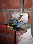
Right now I turn my pump on and off using the circuit breaker (Yeah I know). So I bought a new Intermatic timer to install. So I open my old timer and my electrical box and I see this mess... Where are my Black, red, and green wires? Any help would be appreciated.


257eslg.jpg


f4ied5.jpg


mshnk5.jpg
 
The "green" ground wire is that bare copper wire coming out of the top conduit.

It looks like black and white are powering the timer with 115 volts. The timer then switches the back wire to output on the blue wire.

The jumble in the box is kind of tricky to decode, but it looks like blue and red head to the pump, with red changing color to yellow?
 
It looks like the cable to the pump might have been too short and someone extended the wires with other color wires that they had hanging around. You could live with the existing supply wiring (although don't know how legitimate Romex in conduit is?), but I'd spend an extra $20 at Home Depot and replace the pump and timer wires while you're replacing the timer.
 
gtemkin, just to clarify. Do you think I should replace the wires leading to my pump (Straight to timer). or replace the "extended" connections? If so, which wires should I get? THHN? Sorry - Completely new at this, thanks for the help.
 
Is the black cable coming up to the box the power supply from the circuit breaker box ?? The green wire laying at the bottom should be tied in with the bare copper up at the top. You could use a short piece of wire and wire nut it on so it would reach. It looks like since it's so short they just made sure it got pinched at that corner when the cover goes on. I'd tie it into the bare copper directly.
 

Attachments

  • grounds.jpg
    grounds.jpg
    98.4 KB · Views: 85
gtemkin, just to clarify. Do you think I should replace the wires leading to my pump (Straight to timer). or replace the "extended" connections? If so, which wires should I get? THHN? Sorry - Completely new at this, thanks for the help.

Replace the wires going to the right (timer box), but more importantly, replace the too short cable going to the pump. I believe thats the black jacketed cable going down from the box. The cable is available as SOW rated cable from HD. I'm assuming the supply cable is the Romex in the conduit at the top. For the timer wires I believe most wire now-a-days is dual rated THHN/THWN so it's likely any new wire you get from HD would be that, but any wire marked THHN should be fine.
 
Is the black cable coming up to the box the power supply from the circuit breaker box ?? The green wire laying at the bottom should be tied in with the bare copper up at the top. You could use a short piece of wire and wire nut it on so it would reach. Since it's so short next best thing is to make sure it gets pinched at that corner when the cover goes back on.

No, the black cable is coming from the Pump, but I think it still should be grounded regardless. Just so I make sure I understand correctly, when I'm all done, should it look like this? (Please excuse my poor MS Paint Skills).

2n0spk.jpg
 
Looks correct. The blue is the switched hot output of the timer. The black is the hot input to the timer and the white is the neutral which provides the 110V return for the timer motor.

You may want to have a 3 wire ground termination in which your ground from your supply and your ground to your pump are wire nutted together along with a 3rd short wire that goes to the box. That way when the box cover is removed you don't disconnect your safety ground to your motor.
 
Your diagram is correct for using a 120 volt timer with a 240 volt pump.

Ideally you should get a 240 volt timer, which switches both of the hot wires. That would be wired a bit differently, and would allow you to use a GFCI breaker, which is a really good idea (and required by modern code). Your current setup/diagram will not work with a GFCI.

The timer you got might be 120 volt or 240 volt. Which specific model did you get?
 
Your diagram is correct for using a 120 volt timer with a 240 volt pump.

Ideally you should get a 240 volt timer, which switches both of the hot wires. That would be wired a bit differently, and would allow you to use a GFCI breaker, which is a really good idea (and required by modern code). Your current setup/diagram will not work with a GFCI.

+1 on that.

That timer is 120 volt and would only be a SPST. You could change out the clock motor for a 240 but it still would only switch one leg. For the owner, that means that in the diagram the orange wire leading to the motor, the motor and the blue wire leading back to the timer are HOT all the time even when the timer is off and the motor isn't running. Motor isn't running but the power is still sitting there in the wires and motor.

With the Double Pole (DPST) 240V timer it switches both legs so when the timer is off both legs from the timer to the motor and the motor are all dead. There is no electricity in the circuit past the timer.

I agree, I'd spend the money to get a 240V DPST timer and a GFI breaker for the circuit box and have more protection from something happening that could shock someone.Since you're doing the timer, at least the 240V timer.

Like someone else suggested, tie the green to the bare copper and then add a screw into the box to tie them both to the box independent of the cover screws.

Did you buy a 120 or 240 volt timer ??

First picture is a standard 120 volt breaker and the second is a standard 240 volt.
 

Attachments

  • 120 volt single breaker.jpg
    120 volt single breaker.jpg
    11.8 KB · Views: 48
  • 240 volt breaker.jpg
    240 volt breaker.jpg
    10.8 KB · Views: 47

Enjoying this content?

Support TFP with a donation.

Give Support
Just when I thought I was ready to go! But I really appreciate the advice. I have a 120v timer (to keep it the same as the old), but not big deal. I can return and get a 240v timer. My question is that I currently have a Main breaker that provides power to my Sub-breaker to my box, etc. If I understand correctly, I need to convert the single pole on my breaker into a double pole? Do I need to do it on the main & sub breaker?
 
We should go back and check some fundamental things. We have been assuming that you are running a 240 volt pump. That is certainly what the wiring looks like it is setup for. If we are correct, you must already have a two pole breaker in both the main panel and the sub-panel. If you don't already have two pole breakers in both places, we have misunderstood something and our advice might not apply.
 
To keep it easy, if it's a 240V system all you need to do is put a wire nut on the end of the white wire. It will not be used.

With the 240V timer you will run the black and red to the supply side of the timer and then connect the orange and blue to the load side.

You are done. New timer, all is good. Don't have to do anything more unless you want to add the GFI unit. It isn't needed for the system to work it's just added protection.

The GFI is just a replacement part that replaces the breaker you presently have and then connect one wire inside the breaker cabinet. That part you might want to hire someone to do or watch a couple videos. I'd recommend getting someone more familiar with electricity to do the work inside the breaker box.
So it's two separate things. Replacing the timer and adding a GFI. If your system is already 240V then it's already "double pole" throughout.

- - - Updated - - -

We should go back and check some fundamental things. We have been assuming that you are running a 240 volt pump.

The 240 volt breaker in the main box and the sub box should look like the second picture and a 240V GFI breaker will have a "test" button on it.
 

Attachments

  • 240 volt breaker.jpg
    240 volt breaker.jpg
    10.8 KB · Views: 49
  • 240V GFI breaker.jpg
    240V GFI breaker.jpg
    7.3 KB · Views: 48
I wanted to give an update after everyone's great advice. I was able to wire my new timer (as 240v) and I replaced the wiring for the pump as well, and it looks/works GREAT! Thank you everyone for your help... but you realize that I now how the confidence to hook up a SWG, so that will be my next project. (Might see another post from me soon!) :) :lovetfp:
 
Thread Status
Hello , This thread has been inactive for over 60 days. New postings here are unlikely to be seen or responded to by other members. For better visibility, consider Starting A New Thread.