
Who here are the water hydraulics experts?
- Thread starter Sabot
- Start date
You are using an out of date browser. It may not display this or other websites correctly.
You should upgrade or use an alternative browser.
You should upgrade or use an alternative browser.
mas985 is the local expert. I know enough to keep up with the discussion, but I would hardly call myself an expert.
Why do you ask?
Why do you ask?
I have been researching various pressure control devices which can address a small issue that I have. A quick recap: On a different thread where I am keeping notes on the Liquidator & pH Adjuster, I have found that I have a pressure difference when my solar heater comes on line. When having both the Liquidator and the pH Adjuster installed, I have to have the meter valve and the flow indicator on the pressure side. The connection is between the filter and the solar panels. I have noticed a 1 point difference on the flow indicator when the flow is between 2 and 3 mark on the flow indicator. This is an issue for when the solar kicks on, this bumps up the flow to the chemical feeders up to 3 to 4 respectively. On the pH Adjuster this is not a big deal but on the Liquidator, anything over 3 on the flow indicator will start putting a fair amount of chlorine into my pool.
Not understanding all the physics of water & pressure, I am on a learning curve to understand what is happening. Not knowing exactly what is happening, I am having issues with selecting the right mechanical device which will allow me to control the pressure. There are a number of different types of valves to control pressure such as pressure regulator, pressure reducing, pressure relief, back pressure and so on. Some say I need a pressure regulator. I found one on eBay that I am going to test to see if it will help, it’s a George Fischer V82 valve. (Here is the link: http://www.us.piping.georgefischer.com/ ... 99A2CDD8FA ) I am also looking at this but have not found one yet: http://www.haywardindustrial.com/pages/ ... rv_04.html
Once I find out what I need, the next issue is find a non-metallic pressure regulator that is inexpensive.
Thanks in advance!
Mike
Sabot,
Any chance you could use two pressure feed points Y-ed together before the Liquidator/pH adjuster, one on the solar side of the valve and one on the non solar side? The faster flowing side could have a restriction (Valve, clamp etc.) to slow it down so it produced the same flow as the other. You'd have to have a check valve in each. This seems like it would be a simpler solution.
Any chance you could use two pressure feed points Y-ed together before the Liquidator/pH adjuster, one on the solar side of the valve and one on the non solar side? The faster flowing side could have a restriction (Valve, clamp etc.) to slow it down so it produced the same flow as the other. You'd have to have a check valve in each. This seems like it would be a simpler solution.
On my initial install, I had 1 feed coming off the PVC into a “Yâ€. In fact I had two meter valves right after the “Yâ€. I tried this with no effect on the pressure. It did increase the flow to the other tank but at a very insignificant amount. The valve did have an impact on the “flow†but did nothing on the “pressureâ€. I tried various flow control devices which where inexpensive but all failed to control the “pressureâ€. This is why I am researching and learning about water hydraulics to explain better what is really happening.
I think you are talking about a different configuration. A normal installation has a single pressure tap. I'm suggesting two pressure taps, connected via a Y which then goes to the inlet of the liquidator/pH adjuster. One on the solar side of the valve, and one on the non-solar side. If your setup is either all solar or no solar, then only one of these taps would have water flowing at any time. Since they connect, check valves would be required in each. If I understand correctly, your system supplies more water to the liquidator/pH adjuster when the valve is in the solar position. If you throttle down the solar side tap so it has flow equal to the non-solar tap, then the liquidator/pH adjuster would use a different tap for each valve setting, but both would provide the same flow.
I don't have any drawing tools on this computer or I'd make a sketch.
I don't have any drawing tools on this computer or I'd make a sketch.
The Liquidator works off of the suction on the pump intake and the pressure on the pump outlet to push water through the system. It can be either suction or pressure limited. That is, if the suction is low then only so much water will be drawn out of the Liquidator, regardless of how much is available to come in. If the pressure side is low then only so much water will come into the Liquidator, regardless of how much may be drawn out.
When to solar comes on the resistance to flow increases and so the pressure increases. The pressure increase will also lower the suction somewhat as the flow rate goes down.
Apparently your Liquidator is pressure limited. If it was suction limited the amount of chlorine feed into the system would go down when in solar mode.
You probably don't want to use either of the pressure regulators you mentioned. Both of them require more flow to work than you have available on the Liquidator feed tube. If you installed one of them on the main water flow you would significantly lower the flow rate while in solar mode and force the pump to do unnecessary work maintaining pressure on the high pressure side of the regulator.
I like JohnT's idea. If you draw pressure side water from both the solar and the regular returns, after the solar diverter valve, you can then add an adjustable valve to regulate the flow when in solar mode and adjust it to match the flow when solar is off. To make this work you will also need check valves to prevent water from crossing over from pool return to solar return when solar is off and the other way around.
To add to this, higher chlorine flow will be at least partially offset by the fact that when running the solar, you will always have a faster UV burn-off rate of the chlorine in the pool.
- May 3, 2007
- 16,838
- Pool Size
- 20000
- Surface
- Plaster
- Chlorine
- Salt Water Generator
- SWG Type
- Hayward Aqua Rite (T-15)
My understanding of the Liquidator was that the flow rate was determined more by the suction side than the pressure side which is why they suggest putting the flow meter on the suction side. They use float shut off valves on the pressure side so that it will only fill to a certain level and then shut off. The suction side works in a similar way but will shut off if the level gets too low. Since this is not a pressurized system, the suction side and pressure side are pretty much independent although not completely. Also, since the pressure side has much higher positive pressure than the negative pressure on the suction side, the suction side is usually the limiting factor for flow rates.
So here is what I think may be happening. When a solar system is engaged, two things will happen. The pressure on the return side will rise and the vacuum on the suction side will decrease. Since the liquidator draw rates are determined primarily on the suction side by the pump suction and the valve setting, when the solar is engaged, the chlorine/acid flow rate should decrease. However, since you have the flow rate meter on the pressure side and the pressure is much higher with the solar on, then initially the flow rate meter may make it look like the flow rate has gone up. After the liquidator reaches the max fill level, then the fill valve will start to close and the flow rate should be closer to what the suction side is but it may oscillate some so I am not sure you can really trust the flow rate meter if it is on the pressure side.
So getting the flow rate to be the same with solar on and off may not be very easy to do. I have the same issue with the DIY acid dispensing system I have shown here. By the way, this system works on nearly the same principle as the liquidator except for the dilution on the pressure side.
You could try and reduce the pressure side flow rate so the tank level drops and then the suction side flow rate will reduce some because the float will reduce the flow rates but I think that would be difficult to get right and consistent. As the filter gets dirty, then all of the hydraulics will change and flow rates will change again.
Instead of a pressure regulator, you really need a vacuum regulator. Unfortunately, these are hard to come by with small vacuum levels and chemically resistant to chlorine and acid. I have yet to find one that would work well.
So I think the only solution may be to work with what you have and set the flow rates for the worst case conditon (i.e. solar on) and for the minimum chlorine level needed based on the CYA/chlorine chart. With solar off, the chlorine flow rate will be higher and your residual should climb some but it shouldn't be that much higher and little more chlorine shouldn't be an issue. And if you run with solar on most of the time, then it should have little overall impact.
[EDIT] - Just saw the additional posts while I was writting this so I think we are all on the same page.
- May 3, 2007
- 16,838
- Pool Size
- 20000
- Surface
- Plaster
- Chlorine
- Salt Water Generator
- SWG Type
- Hayward Aqua Rite (T-15)
JohnT said:To add to this, higher chlorine flow will be at least partially offset by the fact that when running the solar, you will always have a faster UV burn-off rate of the chlorine in the pool.
Unfortunately, the chlorine draw rate is less with solar on than off which is why it would be a good idea to set the levels with solar on.
Great info gents! Let's keep testing and reporting what we find. 
I have been watching your build with interest since both of our projects share a similar linage. The same applies to our quest for inexpensive hardware. I have found that once you find the right hardware, no matter the cost head over to eBay. Wheel and deal and you will get the product for a reduced cost. I have a bought a number of things on eBay which I am testing. If bought new, they would cost $400 plus. On eBay I have been able to grab some for $40 - $130 price range. Still too expensive for the average user but at least I can test the principle.
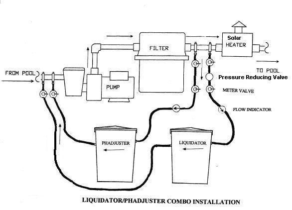
Your understanding on the Liquidator is correct. The meter valve and flow indicator is placed on the suction side of the tank. But when you add the pH Adjuster to the mix, you have to control the flow into tank on the pressure side. I tested both setup to see why and the answer is that the tanks will overflow if the meter valve is installed on the suction side. In order to use the pH Adjuster, the owner must own the Liquidator.
Here is the drawing in the manual on how to hook up the Liquidator and the pH Adjuster:

During my conversation with David Booker, he has always installed his Liquidators with the controls on the pressure side. He stated that there might be some salting issues with the controls if they where mounted on the suction side. (Salting will occur if the pH is out of balance as stated in the manual) David was not aware of the change in the Liquidator’s manual of having the metering device on the suction side. His thought is that HASA did this to conform to the certification process.
I can’t explain it yet but in time I hope to. But my chlorine and acid draw rates increase when the solar comes on line. My end goal is to set the flow rate the same no matter if the solar is on or off.
I think I am going to install a flow indicator on the suction side of the tank as well. Just to see the difference of the flow rate between the pressure side and the suction side. Now a new question, which flow indicator is the most important one to use? :
Agreed, I have been operating on the worst case scenario. During normal operations (non-testing) I set my flow rate to 2.5 on the flow rate indicator for non-solar use. So when the solar comes on line my flow rate is 3.5. Even at this I still see spikes and valleys in FC in the pool. When I see a spike and adjust the flow rate a bit slow and then I start to burn off the excess FC. Then when the FC gets to around 3ppm, I open up the flow rate just a tad and then I get another spike to around 7ppm within one day time frame. (keeping in mind that my pump is running only 10 hours a day. Noon – 8pm and 10pm –Midnight)
Here is how my Liquidator and pH Adjuster is now setup:
I have been watching your build with interest since both of our projects share a similar linage. The same applies to our quest for inexpensive hardware. I have found that once you find the right hardware, no matter the cost head over to eBay. Wheel and deal and you will get the product for a reduced cost. I have a bought a number of things on eBay which I am testing. If bought new, they would cost $400 plus. On eBay I have been able to grab some for $40 - $130 price range. Still too expensive for the average user but at least I can test the principle.
Your understanding on the Liquidator is correct. The meter valve and flow indicator is placed on the suction side of the tank. But when you add the pH Adjuster to the mix, you have to control the flow into tank on the pressure side. I tested both setup to see why and the answer is that the tanks will overflow if the meter valve is installed on the suction side. In order to use the pH Adjuster, the owner must own the Liquidator.
Here is the drawing in the manual on how to hook up the Liquidator and the pH Adjuster:
During my conversation with David Booker, he has always installed his Liquidators with the controls on the pressure side. He stated that there might be some salting issues with the controls if they where mounted on the suction side. (Salting will occur if the pH is out of balance as stated in the manual) David was not aware of the change in the Liquidator’s manual of having the metering device on the suction side. His thought is that HASA did this to conform to the certification process.
I can’t explain it yet but in time I hope to. But my chlorine and acid draw rates increase when the solar comes on line. My end goal is to set the flow rate the same no matter if the solar is on or off.
I think I am going to install a flow indicator on the suction side of the tank as well. Just to see the difference of the flow rate between the pressure side and the suction side. Now a new question, which flow indicator is the most important one to use? :
Agreed, I have been operating on the worst case scenario. During normal operations (non-testing) I set my flow rate to 2.5 on the flow rate indicator for non-solar use. So when the solar comes on line my flow rate is 3.5. Even at this I still see spikes and valleys in FC in the pool. When I see a spike and adjust the flow rate a bit slow and then I start to burn off the excess FC. Then when the FC gets to around 3ppm, I open up the flow rate just a tad and then I get another spike to around 7ppm within one day time frame. (keeping in mind that my pump is running only 10 hours a day. Noon – 8pm and 10pm –Midnight)
Here is how my Liquidator and pH Adjuster is now setup:
Attachments
- May 3, 2007
- 16,838
- Pool Size
- 20000
- Surface
- Plaster
- Chlorine
- Salt Water Generator
- SWG Type
- Hayward Aqua Rite (T-15)
I'm sorry everyone, I had assumed that the metering was done on the suction side and not the pressure side. That changes everything and in fact reverses everything I posted previously. So the increase in flow with pressure when the solar is on now makes sense.
Because you are adding restriction on the pressure side (metering valve), the liquidator is somewhat starved for water and probably is near the minimum water level. You could meter on the suction side but again there will still be a PSI swing and flow change. It could be better on the suction side but it depends on what the current operating parameters are so to know for sure you would have to do some suction measurements.
So probably the easiest solution would be what John had proposed although you would need another metering valve and check valves. Just make sure the flow meter is after the two lines combine otherwise you would need to have two flow meters as well.
However, I would like to point out one additional thing. In my pool, the pressure goes from 20 PSI to 28 PSI with the solar on. This is an increase of 40%. Since the flow rate is approximately proportional to the sqare root of the pressure, flow rate should only increase by 20% or so which is not a lot and should only change 2 ppm residual to 2.4 ppm. So unless, your pressure is changing by much more than that, you really shouldn't have a big change in chlorine levels.
[EDIT] Another thing I just noticed on the drawing was the pressure reducing valve. What type of valve is this? This could have a negative impact as well.
I tried what John suggested with no improvement. From what I understand, the valve will effect the flow rate of fluid not the pressure within the fluid. I believe my issue is the pressure, not the flow rate. This is where my mind becomes fuzzy. ") I did a flow rate study last week:
I did a flow rate study last week:
Solar On
(Setting on the Flow Indicator)
(5) 1m:15sec
(4) 1m:37sec
(3) 2m:28sec
(2) 4m:10sec
(1) 7m:25sec
GPM:
(5) 1
(4) 1
(3) .5
(2) .25
(1) .14
Solar Off
(Setting on the Flow Indicator)
(5) 1m:48sec
(4) 2m:8sec
(3) 3m:01sec
(2) 4m:27sec
(1) 7m:26sec
GPM:
(5) 1
(4) 1
(3) .5
(2) .25
(1) .14
With both the Liquidator & pH Adjuster both running:
Solar On
(Setting on the Flow Indicator)
(5) 49.5sec
GPM:
(5) 1.2
Here is the link to the entire thread: http://www.troublefreepool.com/viewtopi ... highlight=
I did a flow rate study last week: Solar On
(Setting on the Flow Indicator)
(5) 1m:15sec
(4) 1m:37sec
(3) 2m:28sec
(2) 4m:10sec
(1) 7m:25sec
GPM:
(5) 1
(4) 1
(3) .5
(2) .25
(1) .14
Solar Off
(Setting on the Flow Indicator)
(5) 1m:48sec
(4) 2m:8sec
(3) 3m:01sec
(2) 4m:27sec
(1) 7m:26sec
GPM:
(5) 1
(4) 1
(3) .5
(2) .25
(1) .14
With both the Liquidator & pH Adjuster both running:
Solar On
(Setting on the Flow Indicator)
(5) 49.5sec
GPM:
(5) 1.2
Here is the link to the entire thread: http://www.troublefreepool.com/viewtopi ... highlight=
I forgot to ask, would there be anything to gain in research for me to mount a flow indicator on the suction side of the tanks? (I have extras)
Thanks,
Mike
Thanks,
Mike
- May 3, 2007
- 16,838
- Pool Size
- 20000
- Surface
- Plaster
- Chlorine
- Salt Water Generator
- SWG Type
- Hayward Aqua Rite (T-15)
Pressure and flow are interlocked by hydraulics. The more pressure you have on the input to line, the higher the flow rate will be for a given head loss. Metering valves work by introducing a pressure drop or friction loss into the line. Increasing friction loss reduces flow rates for a given input pressure. So you really cannot separate one from the other.
You said you tried what John suggested but that requires another hole in your plumbing after the solar valve and a complete separate line from the hole to a y before the flow meter. In additon, you need another metering valve in that line and the check valves. I just want to make sure we are talking about the same thing. Are you saying you did all of this?
You said you tried what John suggested but that requires another hole in your plumbing after the solar valve and a complete separate line from the hole to a y before the flow meter. In additon, you need another metering valve in that line and the check valves. I just want to make sure we are talking about the same thing. Are you saying you did all of this?
- May 3, 2007
- 16,838
- Pool Size
- 20000
- Surface
- Plaster
- Chlorine
- Salt Water Generator
- SWG Type
- Hayward Aqua Rite (T-15)
Sabot said:I forgot to ask, would there be anything to gain in research for me to mount a flow indicator on the suction side of the tanks? (I have extras)
Thanks,
Mike
Not really, the liquidator will stabilize at the same flow rate on either side.
Sabot said:I tried what John suggested with no improvement. From what I understand, the valve will effect the flow rate of fluid not the pressure within the fluid. I believe my issue is the pressure, not the flow rate.
Since the Liquidator is an open system, it seems to me that flow rate is the only thing to be concerned with. While the pressure affects the flow rate, it doesn't seem like it would matter to the performance of the equipment. I may be overlooking an issue I don't understand.
- May 3, 2007
- 16,838
- Pool Size
- 20000
- Surface
- Plaster
- Chlorine
- Salt Water Generator
- SWG Type
- Hayward Aqua Rite (T-15)
One other thing I think I missed before was that you said the flow rate was 2.5 without solar and 3.5 with solar. Again, this is only a 40% increase and would change the residual from 2 ppm to 2.8 ppm so why worry about it?
- May 3, 2007
- 16,838
- Pool Size
- 20000
- Surface
- Plaster
- Chlorine
- Salt Water Generator
- SWG Type
- Hayward Aqua Rite (T-15)
JohnT said:Sabot said:I tried what John suggested with no improvement. From what I understand, the valve will effect the flow rate of fluid not the pressure within the fluid. I believe my issue is the pressure, not the flow rate.
Since the Liquidator is an open system, it seems to me that flow rate is the only thing to be concerned with. While the pressure affects the flow rate, it doesn't seem like it would matter to the performance of the equipment. I may be overlooking an issue I don't understand.
In the end the flow rate is the most important but the flow rate is dependent on the pressure of the input line so it is the pressure which determines the flow rate.
I'm attaching a couple of rough sketches of what I'm suggesting. Keep in mind that I don't know your system and can't see your pictures. Also keep in mind that the only thing I have to work with is MS Paint.
You may have to select View Picture, then zoom in to see it. This picture is just adding a second pressure tap on the solar side.
The next post has another option in it.
You may have to select View Picture, then zoom in to see it. This picture is just adding a second pressure tap on the solar side.
The next post has another option in it.
Attachments
Thread Status
Hello , This thread has been inactive for over 60 days. New postings here are unlikely to be seen or responded to by other members. For better visibility, consider Starting A New Thread.
Similar threads
- Replies
- 21
- Views
- 891
- Replies
- 9
- Views
- 338
- Replies
- 8
- Views
- 94
- Replies
- 6
- Views
- 446