Help understanding these wires

Jan 3, 2013
126
Hi All,
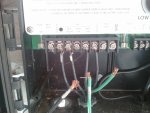
This is a pic of a Heliomatic solar controller and I could use a little help understanding the wiring. I think the "out" wires go to the solar pump, I think the "red" and "black" 240v wires are from the breaker panel and I have no idea what the "slave in" wires are doing. Would be most grateful for any help. Thanks
[attachment=1:im9c9se0]22013-03-16 13.05.22.jpg[/attachment:im9c9se0]
 

Attachments

  • 22013-03-16 13.05.22.jpg
    22013-03-16 13.05.22.jpg
    431.8 KB · Views: 137
Are you trying to understand the existing wires shown in the picture or are you trying to wire it up?

HERE is the manual, although not very helpful.

The "Red and Black" are certainly the power source. I am guessing the the slave, might have something to do with a relay ... like coming from your main power timer so that the main pump has to be on in order for the booster pump to be energized by the OUT terminals. This is only a guess as the manual is not clear.
 
Oh wait. Are you sure you do not have the HM-5000D which says it is capable of controlling a solar pump.

HERE is the 5000 manual ... which confirms terminals 1 and 7 are OUT for the pump, but still does not mention the SLAVE terminals.
 
I had a 4000 but the control board is bad, so I figured I would just get a 5000 and mimic the existing wiring hookup. Problem is the new controller keeps blowing its 5A fuse and I thought perhaps I wired it backwards.
I think you are right about the slave wires. Since the solar booster is only 3/4hp and the main filter pump is 1.5hp, it looks like the previous owners didnt want the solar pump to run without the main.
Confusingly, this new controller worked great for the first day, now blowing fuses. I am confused.
 
I searched but I can't find a manual for it. Do you have a manual? I found the same manuals the JB did.

I think you're right about the wiring, but a manual would confirm it. From what I can find terminals 1 & 7 are to power a solar pump. Terminals 3 & 4 are for 120 volt operation and 3 & 5 if you have 240 volts. Terminals 2 & 6 I can't find any clue about. I would think they may go to a timer or something that prevents the unit from running if that input is not on.
 
jbizzle found the correct manual for the 5000, it is exactly the same as manual that came with the controller and as you can see, a lot of information is missing from the manual.
The "extra" wires are meant to be the "outs" going to the booster pump. They were unhooked at the time of the photograph.
 
Heliotrope General sold/sells a number of different models that all share the same face plate and terminal block. Depending on which model you have various terminals on the terminal block may or may not do anything. On the 4000 series only the power input terminals are active on the high voltage terminal block. On the 5000 series the "out" terminals are relay switched high voltage outputs for controlling a solar pump. As far as I can tell, the salve connections do not do anything on either the 4000 or 5000 series.
 

Enjoying this content?

Support TFP with a donation.

Give Support
There aren't all that many possibilities. You could be supplying too high an input voltage (quite unlikely as you are using the 230 volt inputs), or shorting one of the outputs (which also seems unlikely as I don't see anything attached to any of the outputs), shorting something else somewhere else (but where?), or the controller might be broken.
 
I just looked at the picture again and noticed that you have something wired to the slave connections, which are never really explained in any of the manuals I have seen. I recommend disconnecting those wires and checking to see if that changes anything.
 
JasonLion said:
I just looked at the picture again and noticed that you have something wired to the slave connections, which are never really explained in any of the manuals I have seen. I recommend disconnecting those wires and checking to see if that changes anything.
I will try that. I think that those are used to prevent the solar booster pump from engaging if the main filter pump is not running.
I also think its possible that the booster pump is causing the fuse on the solar controller to blow. Seems like i need to feed power to the controller, then add the slave, then add the booster to see which component is the fuse blower.
 
Thread Status
Hello , This thread has been inactive for over 60 days. New postings here are unlikely to be seen or responded to by other members. For better visibility, consider Starting A New Thread.