Electrical for new Autopilot

budgetplan1

0
LifeTime Supporter
Jan 1, 2013
70
Cleveland, OH
I'm thinking of adding Autopilot SWG this spring. Current equipment (pump/heater) wired 220v to Intermatic T101R timer box. Relatively straight-forward deal. With respect to electrical, where would the Autopilot fit in to this scheme? The manual indicates provisions for wiring to external timer by connectiong to LOAD OUT terminals in timer box but won't this mean that when timer is in OFF condition the Autopilot will have no power to it as well? Don't I want the Autopilot to be 'always on'? Additionally, with pump AND heater already wired to the LOAD OUT of the timer box, is the addition of Autopilot as 3rd LOAD OUT component OK?

I'm just trying to grasp the concept, not that I'd actually do it myself w/ no assistance; I hate electricity.
 
There are a number of different ways to install the AutoPilot unit.

You can simply wire the AutoPilot to the load out side of the timer, and continue using the timer as a timer. Attaching the AutoPilot as a third connection to the load out terminals is fine. Just be careful to make sure you make a solid connection (more difficult with more wires, but not all that bad).

Alternatively, if you are getting the AutoPilot Digital and also get the optional relay you can remove the timer and use the timer inside the AutoPilot unit as the timer.
 
Thanks. So the Autopilot will essentially have no power when timer is in OFF cycle and will power up w/ previous settings when timer hits ON cycle and turns on pump/heater/Autopilot? This will also allow the heater to shut down 15 minutes before everything else via intermatic fireman switch, although the actual need to do that is apparently up for debate. Raypak heater manual states it should be so (cool down period) but I had a Minimax Plus heater run for 16 years with no cool down period. Timer turned off both pump and heater at same time.

So many questions, so many different answers
 
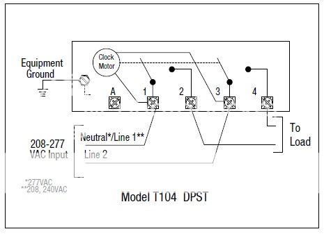
I think it's a T101 case w/ T104 insides. Been around since the pool builder installed it with pool 16 years ago:

How it's wired up, just like the T104 diagram on Intermatic site:
timer_zpse2d19950.jpg


My box:
IMAG0704_zpsac332706.jpg

IMAG0705_zps74e4e832.jpg

IMAG0706_zps1c1781e9.jpg


Heater wires run out lower right side of box, pool pump out of bottom right, line in from panel (double pole breaker) from bottom left.
 
Thread Status
Hello , This thread has been inactive for over 60 days. New postings here are unlikely to be seen or responded to by other members. For better visibility, consider Starting A New Thread.