Suction Line Alignment and useful tricks/techniques

Aug 18, 2012
224
Sacramento CA
How precise must the alignment be?
And before I get lost in minutia: can/should teflon tape (or other thread compound) be used on 2" sch 80 unions?

Now to the main issue:


Given that I have near-zero flex in the line, can I use a flex coupling on the one place where one could possibly be installed?

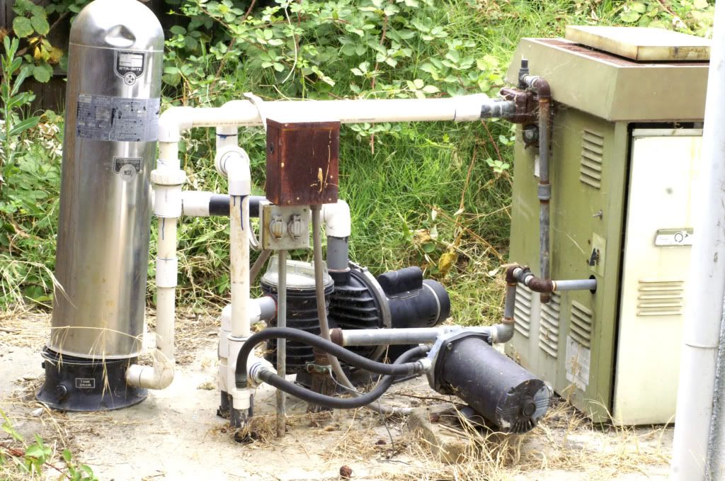
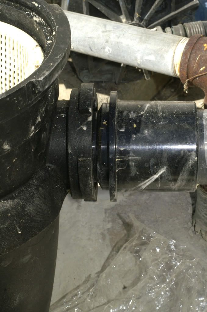
By the time I got here, there was 3" of sch 80 coming out of the ground - from there it was a mass of couplings. I installed a sch 80 2" union onto the exposed original pipe. Given the sizes of sch 80 couplings, there is almost NO space between the union and the el

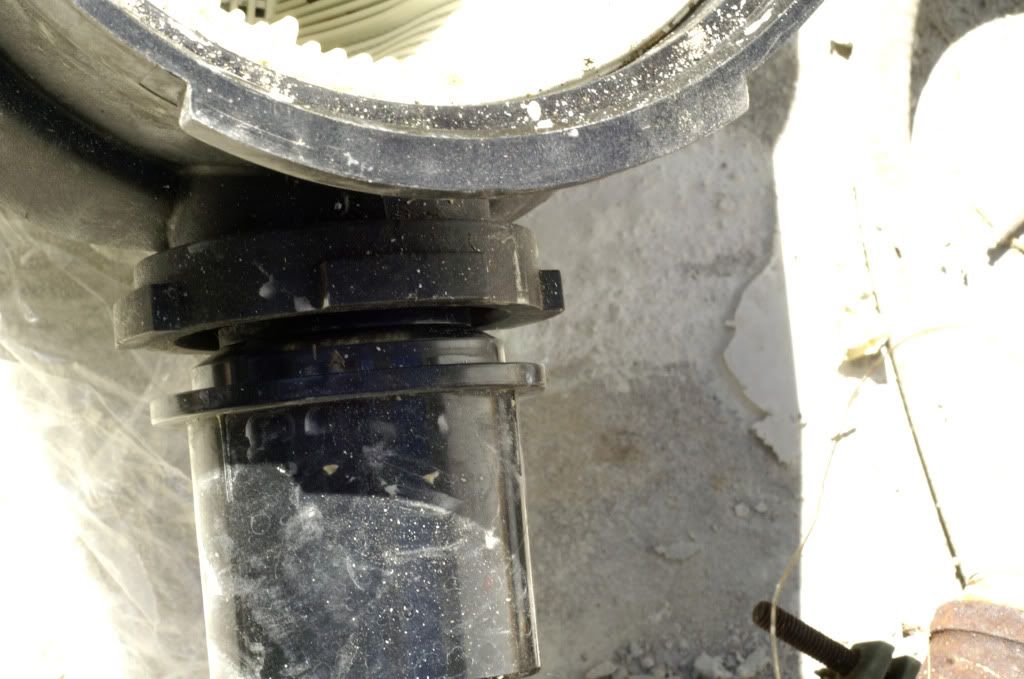
After many days of playing with cement to create a pad to raise the new pump to the suction line, I have the height, but about 5 degree angle between the center line of the pipe and the center line of the Northstar's (poorly designed) union fitting.

I am thinking of first setting line to the pump, then swinging it over the ground-level union - using the sch 80 union to absorb the slack?

When it doesn't, and I still have no money for a pro, could a flex coupler be installed in the horizontal section, providing some slack to absorb the 5 degrees?

Look at the bright side: once I get this (your vulgarity goes here) pump operational, the rest is easy enough that I won't be bothering you nice folks again

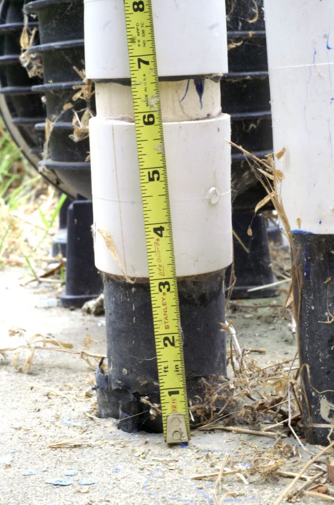
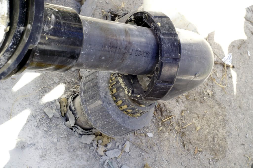
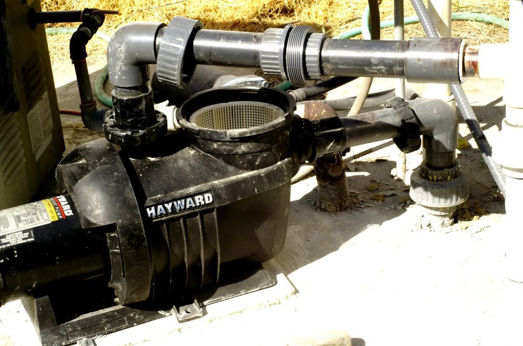
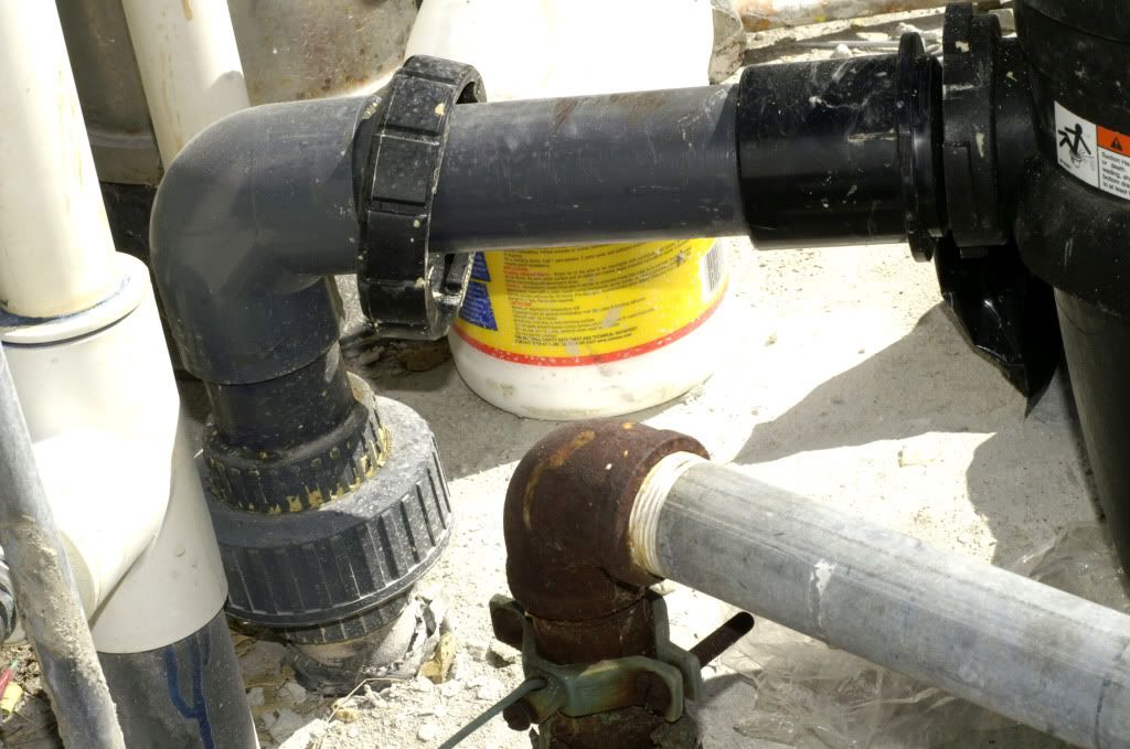
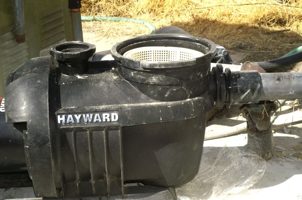
Pics show original setup
bothpumpsandheater.jpg

pipefrompoolorspa.jpg
 
Here are a few I hope will work:
The first is a shot of the entire suction line - not much slack - the horizontal line is where I'm thinking a coupling might work
The second has the pressure line in place just to show how the whole mess is supposed to work
There is one side and 1 overhead view of the couplings slightly apart
The last two are self-explanatory

So: just install o-rings and jam them together?
Use tread dope (and what kind) on sch 80 unions?
Would a flex coupling on the suction line help more than it would hurt?

Thanks again for your time and thoughts

dave

Northstarentiresuctionlineinstalled.jpg

NorthstarOverview.jpg

NorthstarSuctionCoupling09272012.jpg

NorthstarSuctionCoupling09272012topview.jpg

NorthstarSuctionLine.jpg

NorthstarSuctionoverviewnopressurelineorcover.jpg
 
I have not seen that type of fitting to the pump before. Is that where you are worried about the alignment? Is there a gasket for the seal?

BTW, Unions do not require any tape of putty. The seal is caused by the O-ring in the union.
 
This is the Hayward proprietary "union" used on the Northstar from 2003-2007 (as far as I have been able to determine).
There is a 3" O-ring which sits in the socket on the pump. In the third pic, that 45 degree beveled end goes through the O-ring and the square face compresses it.
The reason I hate these is a "a quarter-turn can do anything" mentality - if you turn the union nut more than 1/4 turn, it pops back off - the back of the nut does not have a complete rear side.

(Here is a good shot of the pieces:
www.westsidewholesale.com/hayward-north ... n-kit.html)

Same thing with the basket cover: 1/4 turn - perfect; 26 degrees - try again
Even that shroud-like thing (Darth's old helmet?) has a handle on it with marks showing "open" and "close" - again, 1/4 turn apart.
That's going to be another thread (you simply can't wait, can you? :-D )

The good side is the tapered nose serves as something of a self-alignment; the bad side is it requires that alignment through all 360 degrees - it would be possible to actually lift the pump by tightening the nut.

This alignment issue with the Northstar union is what inclines me to set it first and use the sch 80 (which has a real thread) to absorb any remaining slop

The pressure line now has 3 unions on it - the next slob is going to have a much easier time. (The one you don't see is on the vertical sch 40 from the horizontal run down to the filter inlet)
 
I Didn't Know That (or, how to kill a pump without really tr

I just stumbled onto the usefulness of opening the bleed valve on the filter when starting the pump
I finally got around to reading the manual (when all else fails...)

Now I know that it can take 5 minutes for a pump to "prime"

One more "how stupid can one person be?" Q;

How do I know that it is "primed"? I figured once the flow of water came in with force, it must be primed. 2" of air in the basket notwithstanding.

So - what IS the definition of "prime"? I understand "head" and thought I understood "prime" (fill with water to create an air-tight seal) and "primed" (water is moving). From what I have read, it seems to mean "no more air in basket". Correct?

How does a "self-priming" pump remove the air? Where does it go?
Besides the filter bleed valve, is there any other valve which should be open until the basket is full?
 
Should be no air in the pump. The air gets pushed into the filter or into the pool. Always should open the filter release to purge of air when you have to re prime the system. Every so often I open the valve on the filter to make sure there is no air in it.

Posted from my Droid with Tapatalk ... sorry if my response is short ;)
 
Options - there are few, but there are those...

Another member has been kind enough to chat about this mess and suggests a complete replacement of the suction line.

The second set of pics above are what I have now. The first set was what I started with. My plumbing may not work, but it looks a LOT better than what it replaced.

What now exits has the following issues (besides leaking a ton of air):

1. There is a 5 degree misalignment of the two unions (the standard one on the ground, and Hayward's Northstar-special union on the suction coupling.

2. The entire pump is sitting 7 degrees basket down. It is level left and right.

3. The pump sits on a cement slab approx. 1/2" high. I created this to raise the pump to the suction line. I had started to mount it on wood, then read Hayward's "Thou shalt not" and replaced it with the cement. I have never been good with mud-like substances - my sheetrock work was an exercise in apply, sand, apply, san....

The entire pad can be removed, or I can rent a huge angle grinder and take it down (my 4" grinder is real slow at this).

How should i spend the little time (and less money) to address this?

I cannot remove the ground-level union without then needing to break the pad to get to usable pipe. That is beyond my comfort range.

I had mounted the Superpump on a platform of 2x6's to get it high enough that the line could be used with a pump with a higher suction port.

Can I get away with blowing off the cement (yes, it is cement, not concrete) and shimming it up with wood?

How critical is front-to-rear level?

I take it that the preferred way to install a pump is to get it mounted nice and level, then re-doing the plumbing to mate. I tried to do it backwards.

I made some progress with the liberal application of Vaseline on all mating surfaces on the basket cover and the suction coupling. Hayward specifies the use of 2 layers of teflon tape on all plumbing joints. I have no idea how to use tape on their bizarre "union", but the store-bought will get a layer on top of the thread dope on it now.
 

Enjoying this content?

Support TFP with a donation.

Give Support
And I'm usually such a clever individual...

Nevermind - I'll go back to the supply house that sold me those sch 80 unions and hope they have more - those were the only ones I had seen, and did not realize that they were different than those sold everywhere else.

If I can find one, I'll just get the pump level, then work from the new union up to meet the Hayward part.

The i'll probably be back with another idiot "why doesn't this work?" Q

Thank you all for your time and patience
 
A couple notes.

Unions do not need any tape or putty, the rubber gasket or o-ring makes the seal.

Do not use vasoline on the seals. It is petroleum based and will damage the rubber. Use a pool lube or something designed for rubber seals.

Posted from my Droid with Tapatalk ... sorry if my response is short ;)
 
Overview:
In which the heathen proposes 2 more bad ideas and seeks "worst case" red flags. He can start the pump from 15'.

OK -
The teflon tape didn't work out, but today's experiments indicate that it is the commercial union (or, deities forbid, the valve) which is the source.
There remains a degree or two of misalignment between the mating surfaces of the union - the back is slightly lower than the front. With the male part 1" above ground, testing it has been difficult, but the saran test hints at the front of it as the source.

Bad idea No. 37:
Use very thing wick packing (a string now made of plastic used to wrap the packing nut on some faucets) under the union's O-ring on the front. This stuff squishes down nicely while staying in one peice, and does not age as can putty.

Given that I am using much too much torque on this thing, it has probably deformed as much as it can.

This is likely to be my last attempt to salvage this install * - just bought two replacement unions and an elbow, fresh primer and cement.

Any absolute red flags here? I know it is way off accepted practices, but I'll settle for "ugly but works".


* - actually, since I'll need to cut the Northstar-specific part off and splice it onto the new union and upright, I'll probably use the flex coupler just for the heck of it. The professional supply house sold it to me knowing it was to be used on a pressurized application. No Home Depot on the suction side (their 1 1/2 sch 40 threaded adapter is leaking on the filter. Shock and surprise smiley here.
 
If anyone needs a giggle:

I blew off the install and am starting at the level of straightening the cement pad I built for it.

Found the problem with the original:
My trusty digital torpedo level (circa 1995) was off by 4 degrees. My 2' bubble now says it's real close.

I fear tomorrow when I double-check the no-going-back install of the union at ground level on the suction line - it was set using the torpedo.

I may end up needing an off-level pad after all...
 
For Those Stilli Following This Thrilling Saga...

The union is off level 3 degrees. In the second set of pics, it's the one on the ground. Cutting it off and starting over is not an option.

Before I finaly am able to use the flex connector as intended, I want to try to get the suction line plumb. I have a small bench disc/belt sander.

Has anyone had any experience grinding down PVC/CPCV to correct alignment? The force required to get it plumb deflects the union - way too much to put on the pipe

The only place on the run where the flex connector could be installed is on the horizontal just before the pump - probaly the highest pressure ppe in the system
 
I have used a rubber coupler used on drains lines for my suction. Available at Home Depot or Lowes. Consists of a rubber sleeve with two hose clamps. I used this to eliminate stress to the fittings at the pump suction. As a bonus there is no need for unions!
 
Now you tell me...

Anyway, I tore out all the suction line and re-worked the pressure.

NOTE TO THOSE WHO FOLLOW:
The union I installed (using an inaccurate digital level) was off level by 3 degrees in the plane critical ot the pump. You CAN grind down the end of sch 80 by 3 degrees and cement the piipe to the union with the pipe cocked as needed to get it plumb,

All lines can now be assembled by hand, using the wrench only for the last half-turn on the unions.

Vaseline removed and replaced with Leslie's pool lube. Neat stuff.

It now works - took 20 minutes, but, for the first time in at least 5 years, the system is primed. A couple of pin-head bubbles remain after 4 hours.

Thanks to all, and esp the kind soul who talked me through the basics via PM.
 

Enjoying this content?

Support TFP with a donation.

Give Support
Thread Status
Hello , This thread has been inactive for over 60 days. New postings here are unlikely to be seen or responded to by other members. For better visibility, consider Starting A New Thread.