Hello
So I opened up the panel to check the part number of current limiter so can order a new one just in case as discussed on the other thread. My unit has been working fine, except lately I noticed even when everything showed normal, the voltage displayed in the 30's and the current at 0. My pool, however, seems to get enough chlorine. I am not sure if it's normal.
Anyway, I turned off the circuit breakers first (220v, double switch) to cut pwr from the pump and the Aquarite through the timer, leaving the timer in on position. The timer provides 220v for the pump and 120 for the Aquarite. I removed the board to get the part number and after I put eveything back in place, turned the circuit breakers back on, I heard a strange sound and next thing I saw was smoke coming out from behind the panel. I checked the board and the power circuit was all messed up (The coper contacts from the black and white (source) terminals that lead to the terminals where the wires from the transformer connected to were all burnt and broken up. So I repaired the the power connections temporary with some wires to test again. This time, I turned on the circuit breakers on first but the timer is in off position. And when I turned on the timer, the circuit breakers stripped (why didn't it do this earlier to protect the board?).
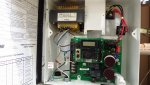
I did a continuity check (pwr off) between the blak and white power terminals and they were ok, not in contact ...until I reconnected either the white or the gray wire from the transformer back to its terminals (see pic). So I left them disconnected and turned the power back on with no problem (of course, the Aquarite isn't getting pwr). There is constant continuity among all the wires: gray, purple, white and blue wires coming from the transformer (is this normal?) and I think because of this, when inplace, it shorted my power circuit.
What went wrong? It's not easy for somthing on the board to be in contact when I reinstalled the board. Did I some how sent 220v to the board by turning on circuit breakers with timer still on? Logically, it's not possible. Did the transformer just coincidently went bad? Is it normal for the wires from the transformer to have constant continuity?
Thanks for any advice
So I opened up the panel to check the part number of current limiter so can order a new one just in case as discussed on the other thread. My unit has been working fine, except lately I noticed even when everything showed normal, the voltage displayed in the 30's and the current at 0. My pool, however, seems to get enough chlorine. I am not sure if it's normal.
Anyway, I turned off the circuit breakers first (220v, double switch) to cut pwr from the pump and the Aquarite through the timer, leaving the timer in on position. The timer provides 220v for the pump and 120 for the Aquarite. I removed the board to get the part number and after I put eveything back in place, turned the circuit breakers back on, I heard a strange sound and next thing I saw was smoke coming out from behind the panel. I checked the board and the power circuit was all messed up (The coper contacts from the black and white (source) terminals that lead to the terminals where the wires from the transformer connected to were all burnt and broken up. So I repaired the the power connections temporary with some wires to test again. This time, I turned on the circuit breakers on first but the timer is in off position. And when I turned on the timer, the circuit breakers stripped (why didn't it do this earlier to protect the board?).
I did a continuity check (pwr off) between the blak and white power terminals and they were ok, not in contact ...until I reconnected either the white or the gray wire from the transformer back to its terminals (see pic). So I left them disconnected and turned the power back on with no problem (of course, the Aquarite isn't getting pwr). There is constant continuity among all the wires: gray, purple, white and blue wires coming from the transformer (is this normal?) and I think because of this, when inplace, it shorted my power circuit.
What went wrong? It's not easy for somthing on the board to be in contact when I reinstalled the board. Did I some how sent 220v to the board by turning on circuit breakers with timer still on? Logically, it's not possible. Did the transformer just coincidently went bad? Is it normal for the wires from the transformer to have constant continuity?
Thanks for any advice