Pump makes noise on Hi when SWG is on, and Lo is off

ncpool

0
LifeTime Supporter
Jul 31, 2010
95
TFP Team:

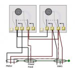
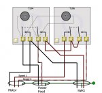
I have a strange issue i need help with. I recently did a self-install of a Circupool RJ45. I wired it into the low side of my Intermatic timer. Now when i run my pump on Hi, and the low switch on the timer box is off, the pump makes a strange noise. The noise doesn't occur if i turn off the SWG, or if i turn on the Lo switch at the timer box (while the pump continues to run on hi).

I have posted a video of this, and i also took a picture of the wiring at the timer. The wires with the blue spade collars are the wires for the SWG.

Please let me know your thoughts. I can provide any other info needed. Thanks in advance.

Here's a video demo of the issue:
http://youtu.be/w8t6R39-hEo

Here's the timer wiring:
J2PtT.jpg
 
Power feed in the center, motor on the left?
Hard to tell for sure, but it appears that the cleaner control timer may be applying power to both HI and LO at the same time.
As Jason said, we'd need a little more info (timer, voltage). A clear pic of the diagram inside the panel could help, too.
 
Everything is 240. The timer is an Intermatic T10404R. I confirmed 240 with a meter when i was installing the SWG.

The power feed is in the center the pump on the left, SWG on the right..

Here is a link for the timer door label, if you need a picture of the inside door instead, please let me know.

Thanks for the help.

door label
 
It is difficult from the photo to be completely sure which wire is going where, but I think I have it figured out.

That is not the recommended way to wire a 240 volt circuit. It looks like you are only using one side of each timer to switch only one side of the circuit, and have the other side hardwired on. It is normal to switch both legs of a 240 volt circuit. Still, while that is a (trivial) safety issue, it shouldn't prevent the system from working.

Regardless of that, nothing in the wiring suggests any problems that might cause a strange noise. Could you describe this noise a little more?
 
Jason, thanks for your help. If you watch the video the noise should be pretty apparent. It isn't happening in the video until i turn off the right manual switch in the timer. The noise starts five seconds into the video. It stops again at 18 secs when i turn the swg off at the swg control center. It is a throbbing noise, almost like a regular pulsating grinding type of noise. In person, it is appears to be coming directly from the motor, which makes sense since it seems to be related to an electrical issue.

I didn't wire the switch, an electrician did that when he wired the pump. It is highly likely he had no idea what he is doing, as i don't think coupling a two clock switch with a two speed pump is a standard configuration around here.
 
I don't think the switch is wired correctly. There looks to be current path through the SWG when the lo switch is off. This could be powering the seconding winding through the SWG while the HS winding is energized. What I think you are hearing is an increase in motor slip because of this.

I think if you rewire both the pump and the SWG so both lines are disconnected on the SWG, this won't happen. In other words move the red SWG line to the empty post on the right.

BTW, is the white line tapped red from the pump the common line?

Also, did the low speed timer work correctly?
 
Here are some more pictures of the wiring. I haven't noticed any issues when running on low. Thanks for everyone's help. I would love to get this thing wired properly. Thanks again.

4JIvE.jpg

FPMim.jpg
 
I don't think it's wired right either. Here's how it appears to me to be wired...
[attachment=0:2sdvvt2q]T1040R_schem_as-wired.jpg[/attachment:2sdvvt2q]

Before discussing the merits of how it should be connected, can I get another pair of eyes to confirm/correct my schematic?
 

Attachments

  • T1040R_schem_as-wired.jpg
    T1040R_schem_as-wired.jpg
    30.1 KB · Views: 211

Enjoying this content?

Support TFP with a donation.

Give Support
I think you may have the wrong timer. The two speed dual timer is T104T06R not T104T104R which is a dual timer but does not the dual speed relays.
 
Ohm_Boy, your diagram matches what I see.

mas985, the T104T104R can be used for a two speed pump as long as one is careful to never have both time clocks turned on at the same time. That isn't ideal, but it can work. However, once we add in the SWG, I am not so sure that will work any more, and you may be correct that a T10604R is required.

Now that mas985 brought it up, I believe that he is correct, there is a current path through the SWG and the low speed winding on the motor (in series) when high speed is active. As far as I can figure out, that would still be true even if the pumps common wire was switched instead of hardwired. The pumps common wire would need to be wired to both right most terminals, and the SWG would thus be half energized at either speed, which would still allow current leakage through the SWG and low speed motor winding.

This timer can be upgraded to be appropriate by getting a T106M (mechanism only) and replacing one of the current timers with the new timer. The setup will be a little different. The T104M will control when the pump is on, and the T106M will control which speed it runs at.
 
I will purchase the T106M unit. I may need some help wiring it up.

I assume i should then wire the SWG to the remaining existing switch which sounds like it will eventually control if the pump is on or off. Is this assumption correct?
 
Yes, the SWG will be wired to the 104 mechanism, and will be on when the pump is on at either speed. The 106 mechanism will also get power from the 104 and will determine which speed the pump runs at. The clock motor on the 106 mechanism will need to be wired slightly differently so it is still powered when the pump is off, but that is simple enough.

There are some other ways to do it, for example the P1353ME, but the approach I mentioned previously seems like the best approach given where you are now.

ncpool, you might want to wait a little bit and see if others agree with me. I am fairly confident, but I didn't figure it out the first time around, so in theory I might still have missed something time as well.
 
Hey Jason...I just hit submit on an order for the T106M assembly was about 80 bucks. Seems like the right way to do this.

I really, really appreciate everyone's help with this. I don't know what i would do without this board.

I will almost definitely need help getting everything wired properly. If anyone has a schematic laying around showing the new 106/104/Pump/SWG setup, i would be very grateful.
 
This should get you going with a 104/106 combo. T104 operated as a DPST "on-off" switch, and controls the motor and SWG. T106 is simply a high speed/low speed selector. Coupla notes - A) both timer motors are wired to #1 and #3 terminals of the T104 timer (the incoming power feed) and B) don't forget the jumper wire between #2 and #3 on T106.

[attachment=0:321eqzbe]T104106_schem_twospd.jpg[/attachment:321eqzbe]
The labels "Speed 1" and "Speed 2" are ambiguous, either can be hi or lo, so you can just flip a coin. Hi time vs Low time is set by the dial trippers.
 

Attachments

  • T104106_schem_twospd.jpg
    T104106_schem_twospd.jpg
    32.3 KB · Views: 178
TFP Team:

Just a quick update on this issue. I installed the T106M unit in my existing box today. I wired everything up per Ohm's schematic.

Everything works perfect now. No noise from the pump on either speed, the SWG works perfectly regardless if the pump is running in high or low speed.

I can't thank you guys enough for finding the issue, and explaining how to resolve. Big thanks again to Ohm for providing the schematic. There is no way i could have done the install without it.

Thanks again guys. Great job.
 

Enjoying this content?

Support TFP with a donation.

Give Support
Thread Status
Hello , This thread has been inactive for over 60 days. New postings here are unlikely to be seen or responded to by other members. For better visibility, consider Starting A New Thread.