P1353ME wiring question for newbie

Feb 13, 2012
11
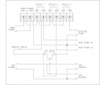
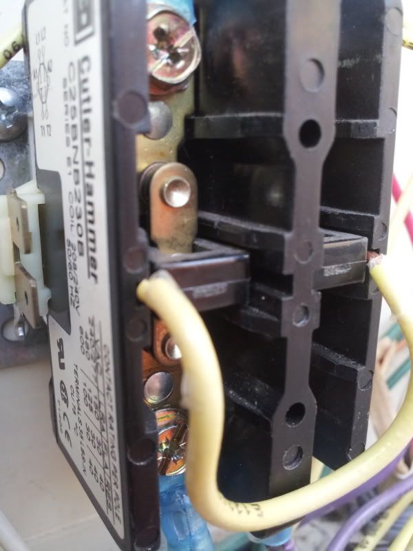
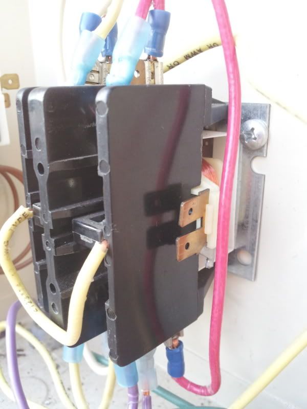
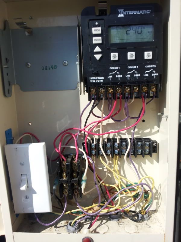
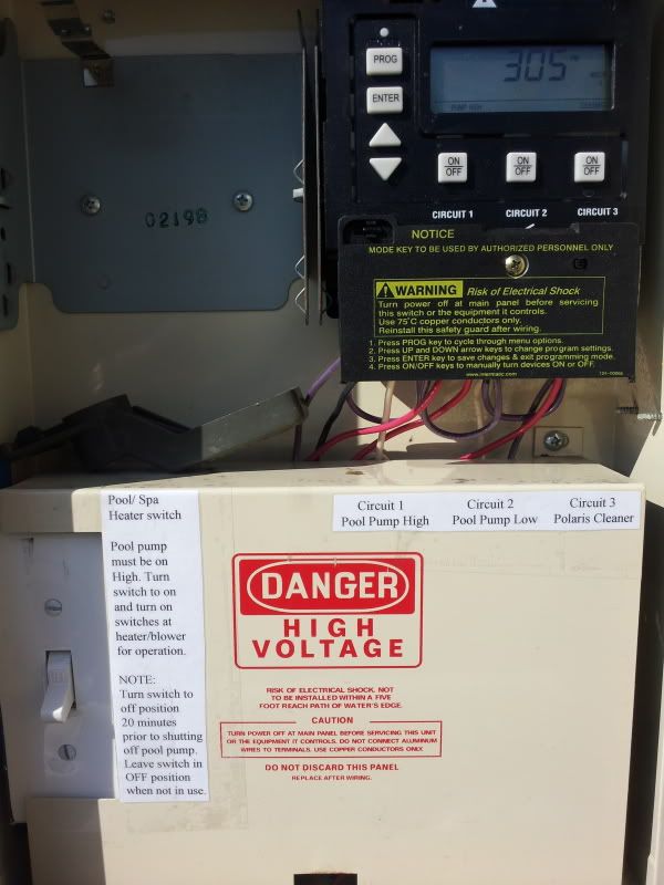
My system consists of a 2 speed pump motor, polaris booster pump, pool/spa heater, blower. With my old single speed pump I had 2 intermatic mechanical timers that controlled everything. I have since replaced them with a single intermatic P1353me 3 circuit timer. I have it set to mode 4 to control the pump high, pump low and booster pump. The blower is wired directly to 220, I have not hooked up my heater yet and would like to have the heater available to come on when the pump is on high speed only. There is a on/off switch at the heater I would use to turn it on when needed. I used the old relay contactor for a junction block/bridge with a jumper wire contecting the lower terminals to the upper terminals and also used a piece of wiring to hold down the mechanical contacts as a redundant contact. All the items are 220v.

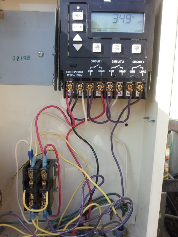
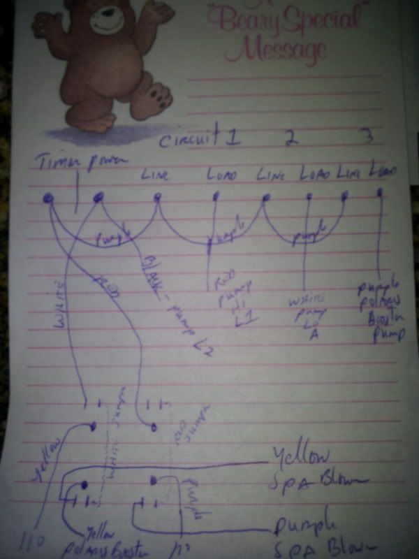
Would it be ok to just run one leg of the heater to line and the other to load on circuit 1? The old timer shut off both lines to the heater. I thought about switching my booster pump input line with the other 110 line and then hooking up the heater to circuit 1 load and circuit 3 load. That way I could turn on the polaris pump which turns on the high speed pump and both circuits would supply power to the heater.

I tried looking for some other type of bridge to use but my local Lowes was no help so I used what I had available at the moment, thats why I used the old contactor relay block.

20120210_142435.jpg

20120210_154848.jpg

20120210_162529.jpg
 
99ssconv said:
Would it be ok to just run one leg of the heater to line and the other to load on circuit 1?
No! One leg on line and the other on load will give you a zero voltage potential when the contacts are made.

I'm not sure what you're trying to accomplish by running through both sets of contacts.
Are you wanting the run the heater and the blower through different contacts?
Do you want to keep the Booster pump on circuit 3?

This is how I would wire it.
[attachment=0:1mgyey3s]P1353ME Wiring Diagram.jpg[/attachment:1mgyey3s]
 

Attachments

  • P1353ME Wiring Diagram.jpg
    P1353ME Wiring Diagram.jpg
    93 KB · Views: 226
The way I have it wired, the heater and blower can't run unless the pump is running in HI speed. You can flip the manual switch but unless the pump is running in HI speed it won't operate. The only drawback in that wiring is that if you leave the switch on then the heater will start as soon as the pump switches to HI. If the aux relay has a third set of contacts you can use pushbuttons to start and stop the heater & blower and it will drop out the seal-in when the pump stops or switches to LO. That way it won't restart when the pump starts or switches back to high.
 
Very nice schematic, the aux relay you are using has 110v on L1 and 110v on L2. How does this energize the relay? I'm used to working with automotive schematics and that wouldn't work in my field. Can you give me a brand and part numberof that relay please. Thanks for your help. The pool heater has its own off/on switch as well as the spa blower but I do like your idea of using a switch on L1 for safety so the pool heater its not accidentally turned on.
 
Since it's only 2-pole you won't be able to use pushbuttons but you can use the diagram I posted.

L1 & L2 on the diagram in the Aux Relay is the coil. They hook to the terminals on each side of the contactor. Even though it has twin terminals on each side you'll only use one of them.

Take that yellow jumper you're using to hold the contactor closed and use it as the jumper shown on the left side in the drawing. Hook it to the top terminals and run hot for your power source into one of them.

Come out the bottom on the left side to the heater and come out of the right side to the blower.

Hook L2 from the power source to both the blower and the heater.
 

Enjoying this content?

Support TFP with a donation.

Give Support
What's the best way to connect the circuits together, like where you have 4 wires and 3 wires. Would you use a twist wire nut? I had a wire nut on three of the 12 gauge wires connected before and it didnt feel or look like a permanent install to me. Looked like a problem waiting to happen. What would you suggest. Thanks for your help, Sunday I will finish this project.
 
Thread Status
Hello , This thread has been inactive for over 60 days. New postings here are unlikely to be seen or responded to by other members. For better visibility, consider Starting A New Thread.