I think you're right -- I just need to keep the family from showers/washing dishes while filling (I'll do my part!)

Stever's Pool Build
- Thread starter stever
- Start date
You are using an out of date browser. It may not display this or other websites correctly.
You should upgrade or use an alternative browser.
You should upgrade or use an alternative browser.
G
Guest
stever said:I think you're right -- I just need to keep the family from showers/washing dishes while filling (I'll do my part!)
you will want to do that regardless though to try and save water for a while. i know if i drained my pool and had to refill i would be takeing showers at the in laws.
Ok - I need a little advice -- a second opinion - or both. My PB has sketched up (and I put on CAD) the schematic for the pool/spa piping (see first page of this thread). He said he had to do this a 'new' way to get the Intelliflow VS to work as the single pump for a pool/spa combo.
He has both returns and jets for the spa. He said that all 120-150 GPM would not work well through the heater and filter and is routing part of the flow to the filter/heater and the rest to the jets. (I have 3" piping to the jets and from the spa drains).
I just found that the minimum flow for the 400,000 BTU heater is 40 gpm. I don't know how much head I will have in the end, but figure I'll max out the VS at 140-150 gmp. subtracting 45 (a little extra to keep it safe) gpm for the heater, that might only leave 95 gpm (worst case??) for the 8 jets -- that's 12 gpm per jet or 20% less than the 15 gps per jet I was told I needed.
- Is it typical to have seperate returns and jets to the spa?
- Will I have enough flor for both the heater and the spa jets?
- Is there a better way? How are yours plumbed?
Thanks!
Steve
It is not uncommon to have a separate return to the spa, normally used for heating and to provide water for the overflow when in pool mode. This typically happens in a two pump split system, where the pool pump has the heater and the spa pump feeds the jets. Such a system would typically have two sets of drains in the spa, each set feeding one of two pumps but otherwise looking much like the setup you have in the diagram. Heated and filtered water from one pump would return to the spa through a return while high flow water from the spa pump would go to the jets.
Given your pump and flow requirements it might be better to plumb things more like a two pump shared heater system. In that setup the spa pumps output is split and part of it goes through the filter and heater while part of it bypasses to maintain high flow rates. Then the flow recombines to feed the jets at the full flow rate.
The way the plumbing is drawn now you will be right on the edge of the pumps operating envelope to try and meet the full flow requirements. That is a bad thing, since even if the pump will push 160 GPM, it will be using peak power to do so. With the WhisperFlo you can push it beyond the edge of the diagram to higher flow rates at the cost of some overheating and shortened pump life. The IntelliFlo is probably too smart for that and will presumably shut down before you get the flow you really want.
You don't want the full flow going to the filter and heater. It would be too expensive to get a filter big enough to handle that and even then it would be a waste since you don't need that much filtering and the extra head of the filter/heater would cost electricity.
You only really need 8 times 15 GPM total, or better yet 8 times 18 GPM to overdrive the jets when desired. That is 120 to 144 GPM, which the IntelliFlow can do. To get that you need the water from the heater feeding the jets along with the water that bypasses the filter/heater. That is quite possible, but isn't what is in your diagram.
This setup would use an automatic valve to split some of the water around the filter/heater and then recombine the water after the filter/heater. From there another automatic valve would split it again to the pool and spa. All of the spa water would feed the jets, no spa return would be required. In pool mode the filter/heater bypass is turned off and only a little water goes to the spa for overflow. In spa mode the filter/heater bypass is turned on and the pool return is turned off.
- May 3, 2007
- 16,823
- Pool Size
- 20000
- Surface
- Plaster
- Chlorine
- Salt Water Generator
- SWG Type
- Hayward Aqua Rite (T-15)
stever said:Ok - I need a little advice -- a second opinion - or both. My PB has sketched up (and I put on CAD) the schematic for the pool/spa piping (see first page of this thread). He said he had to do this a 'new' way to get the Intelliflow VS to work as the single pump for a pool/spa combo.
He has both returns and jets for the spa. He said that all 120-150 GPM would not work well through the heater and filter and is routing part of the flow to the filter/heater and the rest to the jets. (I have 3" piping to the jets and from the spa drains).
I just found that the minimum flow for the 400,000 BTU heater is 40 gpm. I don't know how much head I will have in the end, but figure I'll max out the VS at 140-150 gmp. subtracting 45 (a little extra to keep it safe) gpm for the heater, that might only leave 95 gpm (worst case??) for the 8 jets -- that's 12 gpm per jet or 20% less than the 15 gps per jet I was told I needed.
I can give you a rough guess as to your head and flow rates but I need some more information see the questions at the end.
- Is it typical to have seperate returns and jets to the spa?
My pool is plumbed that way and it is usually a good way to get higher flow rates for the jets.
- Will I have enough flor for both the heater and the spa jets?
Possibly but I can give some numbers with the additional information.
- Is there a better way? How are yours plumbed?
My jets are on a separate pump and suction lines. It usually is not a good idea to have very high flow rates through a filter and heater. Filters are less efficient and heaters usually have an upper limit of 120 GPM after which they require a bypass. The configuration in the drawing is probably the only way you will get the full flow rate for the jets.
Thanks!
Steve
I have a full head model which includes the Intelliflo pump. I can usually get close enough to actual flow rates. Most of the plumbing parameters I can get from your drawing but need some additional information to model the pool.
The drawing you gave has the diameters of the pipes but not the lengths. So about how long are the runs from pad to pool, suction and return, pool and spa? Also, are all the lines single lines as shown on the drawing?
One additional concern is that he has used 2.5" plumbing on the spa suction line but 3" on the return lines. The jets will add a lot of head on the return side so there should be more head on the return side but for the high flow rate of the spa, I would have put 3" lines on the suction as well. He probably figured they were short enough not to matter.
JasonLion said:It is not uncommon to have a separate return to the spa, normally used for heating and to provide water for the overflow when in pool mode. This typically happens in a two pump split system, where the pool pump has the heater and the spa pump feeds the jets. Such a system would typically have two sets of drains in the spa, each set feeding one of two pumps but otherwise looking much like the setup you have in the diagram. Heated and filtered water from one pump would return to the spa through a return while high flow water from the spa pump would go to the jets.
I have 1 set of drains in the spa and a one-pump system.
Given your pump and flow requirements it might be better to plumb things more like a two pump shared heater system. In that setup the spa pumps output is split and part of it goes through the filter and heater while part of it bypasses to maintain high flow rates. Then the flow recombines to feed the jets at the full flow rate.
I like that a lot better -- then I'd get the full pump flow to the jets. When the flows recombine they will get the power needed. In pool mode, the returns would be on and not the jets and in spa mode the jets would be on and not the returns.
You don't want the full flow going to the filter and heater. It would be too expensive to get a filter big enough to handle that and even then it would be a waste since you don't need that much filtering and the extra head of the filter/heater would cost electricity.
I agree with this -- I have a 60 sf DE filter planned -- it'd blow up with 160 gpm!
This setup would use an automatic valve to split some of the water around the filter/heater and then recombine the water after the filter/heater. From there another automatic valve would split it again to the pool and spa. All of the spa water would feed the jets, no spa return would be required. In pool mode the filter/heater bypass is turned off and only a little water goes to the spa for overflow. In spa mode the filter/heater bypass is turned on and the pool return is turned off.
Thank you very much -- you have reconfirmed my fears, but it's not too late to do the right way!
mas985 said:stever said:Ok - I need a little advice -- a second opinion - or both. My PB has sketched up (and I put on CAD) the schematic for the pool/spa piping (see first page of this thread). He said he had to do this a 'new' way to get the Intelliflow VS to work as the single pump for a pool/spa combo.
He has both returns and jets for the spa. He said that all 120-150 GPM would not work well through the heater and filter and is routing part of the flow to the filter/heater and the rest to the jets. (I have 3" piping to the jets and from the spa drains).
I just found that the minimum flow for the 400,000 BTU heater is 40 gpm. I don't know how much head I will have in the end, but figure I'll max out the VS at 140-150 gmp. subtracting 45 (a little extra to keep it safe) gpm for the heater, that might only leave 95 gpm (worst case??) for the 8 jets -- that's 12 gpm per jet or 20% less than the 15 gps per jet I was told I needed.
I can give you a rough guess as to your head and flow rates but I need some more information see the questions at the end.
- Is it typical to have seperate returns and jets to the spa?
My pool is plumbed that way and it is usually a good way to get higher flow rates for the jets.
- Will I have enough flor for both the heater and the spa jets?
Possibly but I can give some numbers with the additional information.
- Is there a better way? How are yours plumbed?
My jets are on a separate pump and suction lines. It usually is not a good idea to have very high flow rates through a filter and heater. Filters are less efficient and heaters usually have an upper limit of 120 GPM after which they require a bypass. The configuration in the drawing is probably the only way you will get the full flow rate for the jets.
Thanks!
Steve
I have a full head model which includes the Intelliflo pump. I can usually get close enough to actual flow rates. Most of the plumbing parameters I can get from your drawing but need some additional information to model the pool.
The drawing you gave has the diameters of the pipes but not the lengths. So about how long are the runs from pad to pool, suction and return, pool and spa? Also, are all the lines single lines as shown on the drawing?
One additional concern is that he has used 2.5" plumbing on the spa suction line but 3" on the return lines. The jets will add a lot of head on the return side so there should be more head on the return side but for the high flow rate of the spa, I would have put 3" lines on the suction as well. He probably figured they were short enough not to matter.
I'll get the measurements in the next day or so -- thanks.
The spa suction is 3" -- I mis-typed it ont he chart. (I had 3" in my contract, and happened to stop by as they wewre putting in 2.5" -- the plumber was doing the 'normal' job instead of looking at the plans. Needless to say I had them pull it out and replace with 3").
Yes, the filter (60 sf DE) heater and SWG don't want more than 120 or so gpm -- I could do it, but why? As you said I don't need that much heatiing, filtering, etc.
I have returns in the spa.... so the setup you mention will not work for me as I'd choose not to abandon them. As I mentioned above, I will have the returns on (no jets) for pool mode and jets on for spa mode (no returns) with the return combined witht the jets.
Will the high GPM in the jets try to push the water backwards in the pipes where they recombine? Seems like the 120 gpm would try to fight with the 40 gpm. (but it's been 20 years since I took my hydraulics course.)
Thanks JasonLion & mas985 -- I'll draw up a revised schematic and post it for your review.
Steve
stever said:Will the high GPM in the jets try to push the water backwards in the pipes where they recombine? Seems like the 120 gpm would try to fight with the 40 gpm. (but it's been 20 years since I took my hydraulics course.)
No. The flow starts out balanced before you split for the filter/heater and the bypass. Then you adjust the dynamic head, by adjusting a valve, so that the flow you want goes through the heater/filter. Everything remains in balance when they recombine. Conceptually it is the same as splitting to two pipes, one of which is large and the other small, and then bringing the pipes back together again. The flow in each pipe depends on their relative size. We adjust the apparent pipe size of the filter/heater path using a valve.
The valve that adjusts the dynamic head/apparent pipe size can simply be the automatic valve that turns the bypass on and off. You use one of the stops to prevent it from fully closing the filter/heater path. You just need to figure out which of the stops gives you the most appropriate flow rate split. Or you could do it with a full travel automatic valve and a bypass with a manual valve, which costs a little more but gives you more precise control.
Thanks for the lesson -- it makes sense (now).
I plan to have a full-motion automatic valve with a seperate manual valve bypass -- I figure a partially open valve will have more head loss than a fully open one -- and with the manual valve bypass, I'd be getting full auto plus partial manual -- more than a single valve by itself.
Steve
I plan to have a full-motion automatic valve with a seperate manual valve bypass -- I figure a partially open valve will have more head loss than a fully open one -- and with the manual valve bypass, I'd be getting full auto plus partial manual -- more than a single valve by itself.
Steve
- May 3, 2007
- 16,823
- Pool Size
- 20000
- Surface
- Plaster
- Chlorine
- Salt Water Generator
- SWG Type
- Hayward Aqua Rite (T-15)
Here is the problem with what you are suggesting. The resulting head loss between the two paths must be the same. Therefore the flow rates will be significantly different. Here is a simple example:
For the bypass route, lets assume a 5', 2" straight pipe (worst case). For the filter route, here is what I have on my pad which shouldn't be too much different than what you have since I have close to the same setup:
Filter: 70' equivalent 2" pipe (when clean)
Heater: 140' equivalent 2" pipe
Pipe: 5' 2" pipe
Fittings: 65' equivalent 2" pipe
So you are looking at about 280' of equivalent pipe compared to 5' in the bypass route so the flow rate ratio will be:
Using Hazen-Williams approximations: GPM (Bypass) / GPM (filter)= (280/5)^(1/1.852) = 8.8 : 1
So the bypass route will have 8.8x the flow of the filter route. If the maximum flow is 160 GPM (assuming you can actually get that), then the filter route will be 16 GPM and the bypass route will be 144 GPM. Not enough flow for the heater. If you use 3" pipe for the bypass route, the problem is even worse. To get to 40 GPM in the filter route, you will have to restrict the bypass route even further.
[EDIT] Forgot to finish. So if you need 120/40, then the flow rate ratio needs to be closer to 3 : 1 so the equivalent length ratio will be 7.6 : 1 or 40' of 2" pipe for the bypass.
[Edit^2] Ran some numbers for this and it could work. I assumed pipe lengths of 35' for the spa. With the Spa independent and completely bypassing the pad, the flow rate should easily achieve the 160 GPM maximum and may go over it assuming the pump can handle it. With the 40' of 2" eqivalent pipe, the flow rate drops to 154 GPM so there is a chance this may work. With some hard numbers on pipe lengths and fittings, we could refine these numbers somewhat.
The three way valve that splits between the filter and bypass can be adjusted to restrict the bypass, so any necessary adjustments can still be done the same way I proposed as long as the total flow works.
- May 3, 2007
- 16,823
- Pool Size
- 20000
- Surface
- Plaster
- Chlorine
- Salt Water Generator
- SWG Type
- Hayward Aqua Rite (T-15)
It does look like it should work but one of the key factors that will determine if this works or not is the type of jet used. A standard gunite venturi jet would require 15 GPM @ 15 PSI. Some jets require up to 25 GPM at 18 PSI. One thing that would be very helpful to know is what type of jet you are using and what the specs are.
In my previous post, I didn't include enough pressure loss in the jets. If I use the 15 GPM/15 PSI numbers which results in 120 GPM total flow, this equates to approximately the same head loss as 1100 feet of 3" pipe. Including that in the model, makes the flow rate more like 138 GPM at maximum RPM or over 17 GPM per jet still more than enough.
Adding the bypass and recombine with restriction on the bypass route, then the flow rate will drop to 134 GPM or bit less than 17 GPM per jet, still good.
Mind you this is all speculation at this point since there are a lot of details missing but it might be worthwhile to make sure this will work before commiting to a design.
I'll measure the pipe runs --
I do not doubt you, but it seems counterintuitive to have to restrict the flow to get more flow.... I must plead ignorance (I know just enough to be dangerous --- well --- maybe not quite that much) on this so thank you for your patience.
I believe I must recombine to get the jet flow I need -- I just must figure out the eest way to do it.
I do not know the specs ont he jets -- I was told by the PB that they are the 'standard' ones w/o adjustable eyes and would require 15 gpm flow (thus 120 gpm would be fine after being combined).
Steve
- May 3, 2007
- 16,823
- Pool Size
- 20000
- Surface
- Plaster
- Chlorine
- Salt Water Generator
- SWG Type
- Hayward Aqua Rite (T-15)
By restricting the bypass route, it increases the flow in the filter route. However, the total flow is reduced when you do this. Maybe this will help.
Option one:
Bypass flow: 138 GPM (port open)
Filter flow: 0 GPM (port closed)
Total flow: 138 GPM
Option two:
Bypass flow: 94 GPM (restriction reduces this flow)
Filter flow: 40 GPM (but increases this flow)
Total flow: 134 GPM
The more the bypass is restricted, the more will flow through the filter.
Ok -- I don't know how to get the across using text... but here goes.
There are twi identical 3" diameter pipes form the pad to the spa for suction and return. From the pad vertical is the 90 deg fitting and then 40 feet of pipe (each) to the spa. Within this 40 feet are 2 pairs of 45 deg fittings on each pipe (8 total).
At the spa, the return has a 'tee' fititng to the 'loop' around the spa. The loop is about 25 feet around and is (I think) 2" pipe.
The suction has a 90 deg fitting at the spa, turns down 3 feet, 90 degree fitting at the bottom, 4 feet horizontal pipe, 45 degree fitting, another 1 foot pipe, then a 'tee' then 18 inches of pipe each direction to 90 degree fiitings up to the drains. Everything in this paragraph totals 11 feet of pipe, 4 90 degree fittings, 1 45 degree fitting and 1 'tee'.
The pool equipment pad is about 12 inches above the water level of the pool and 12 inches below the spa water level.
I hope this helps (you help me!).
Steve
Mark,
Sorry -- I got it (I feel dumb) . I heard 'bypass' and thought of the filter route -- I mis-read it making it seem that the more restrictive the 'filter' route was the more flow it would get. My mistake. Yes, the more restrictive the jet (bypass) is the more goes to the filter/heater.
But if I plan an automatic valve to be full open in spa mode for the bypass and a manual valve piped around the automatic valve you bring up a good point. This would not allow me to restrict the 3" spa/bypass route enough and even if the manual valve was full open it would not get enough through it. I guess I could cam-stop the automatic valve.
Steve
mas985 said:By restricting the bypass route, it increases the flow in the filter route. However, the total flow is reduced when you do this. Maybe this will help.
The more the bypass is restricted, the more will flow through the filter.
Sorry -- I got it (I feel dumb) . I heard 'bypass' and thought of the filter route -- I mis-read it making it seem that the more restrictive the 'filter' route was the more flow it would get. My mistake. Yes, the more restrictive the jet (bypass) is the more goes to the filter/heater.
But if I plan an automatic valve to be full open in spa mode for the bypass and a manual valve piped around the automatic valve you bring up a good point. This would not allow me to restrict the 3" spa/bypass route enough and even if the manual valve was full open it would not get enough through it. I guess I could cam-stop the automatic valve.
Steve
- May 3, 2007
- 16,823
- Pool Size
- 20000
- Surface
- Plaster
- Chlorine
- Salt Water Generator
- SWG Type
- Hayward Aqua Rite (T-15)
Your numbers were pretty close to what I guessed so the flow rates change by less than 1 GPM. Most of the head loss occurs at the jets which is exactly what you want.
At 135 GPM, suction head is about 5.8' and return head (with jets) is about 53' of head with total head at about 59. The jets alone are about 48' of head.
There is quite a bit of margin here so even if I got something wrong, I think you would still be ok. In fact, I can add 100' of 2" pipe, and the flow rate will still be above 120 GPM.
mas985 said:At 135 GPM, suction head is about 5.8' and return head (with jets) is about 53' of head with total head at about 59. The jets alone are about 48' of head.
Does that mean there is 101 ft of total head on ths spa between the suction and return? I looked at the chart for the VS pump and that is above the 'maximum' line. Nothing with my setup is that weird.... so I'd guess that I just nead some educating -- what am I missing?
Also, here is the latest iteration of the piping diagram taking all the messages to heart. The three numbers listed are GPM for pool, heat pool and spa (respectively). I am assuming 20 gpm for the pool operation without heat just for discussion purposes. I need 40 gpm for the pool heat -- no reason for any more. And I threw in 140 gpm for the spa, though this could be as low as 120 GPM if I understand you correctly (and could tune the bypass just right).
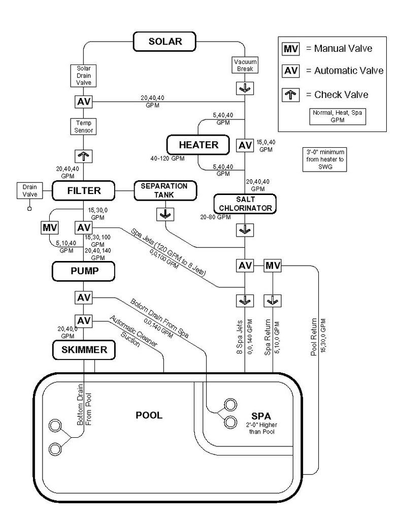
- I have used the spa returns for the spa spillover but turned tham off for spa mode (jets only).
- I have a manual valve to balance the pool/spa (as most of you do) now that the 3-way automatic valve switches jets vs pool&spa instead of spa return vs pool return as before.
- There seems to be a lot of check valves (these are my thoughts, not plumber's). I can't jsutify taking them out, as I don't want the seperation tank flowing back into the SWG (??) or the normal operation flowing into the seperation tank (??). The others are (I think) normal -- two for the spa (return and jets) to prevent it from emptying into pool when pump is off. One on the solar. One after the filter.
Is it good?
Steve
I don't see any reason for the check valve just above the filter.
You aren't showing the main valve on the filter. The "drain" from the filter is typically called waste and should not have a valve on it (other than the main valve).
You show the main pool drain plumbed to the skimmer. Ideally the pool drain and skimmer should run in separate pipes to the equipment pad, though it will work the way you have it drawn.
mas985 was talking about 100 feet of pipe, not feet of head. They are related in a complex way that makes it simpler to talk in one unit for some purposes and in the other unit for other purposes.
JasonLion said:I don't see any reason for the check valve just above the filter.
I show this because I have seen it before in schematics -- but you are right -- once I have one after SWG later in the circuit, it's useless.
You aren't showing the main valve on the filter. The "drain" from the filter is typically called waste and should not have a valve on it (other than the main valve).
Correct again -- I should not call the drain a valve -- it's just 'there'.
You show the main pool drain plumbed to the skimmer. Ideally the pool drain and skimmer should run in separate pipes to the equipment pad, though it will work the way you have it drawn.
Unfortunately I did not know enough about this until it was too late. The main drain is hooked up to the skmmer with a little rotating flappy thing to somehow regulate the flow. I have pretty good piping to the spa but so-so plumbing to the pool (2" to the skimmer/main drain and 2" back to the 4 returns). I'm not too broken up about this as the difference in efficiency will most likely be minor at slower speeds. (plus it't too late!)
mas985 was talking about 100 feet of pipe, not feet of head. They are related in a complex way that makes it simpler to talk in one unit for some purposes and in the other unit for other purposes.
Roughly how do I take this into to the pump charts? Is there a rough conversion factor I can use?
Thanks!
Thread Status
Hello , This thread has been inactive for over 60 days. New postings here are unlikely to be seen or responded to by other members. For better visibility, consider Starting A New Thread.