I am changing out my pool equipment and so I decided to redo the wiring also.
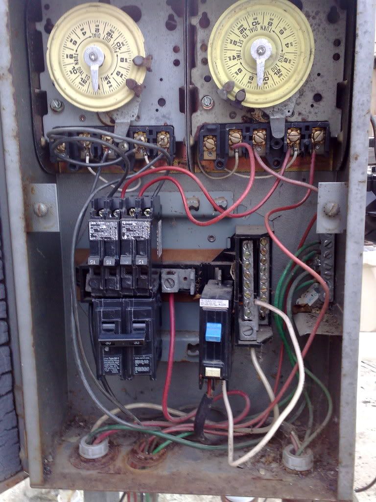
The second picture is an image of the breaker box located next to my pool. The lower left is where the main wires come in, I have one black and one red wire that are used to run the pump, there is a white wire that is for the lights and one green wire for grounding.
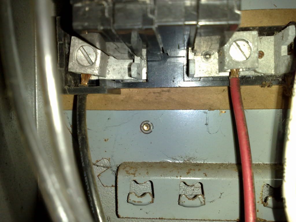
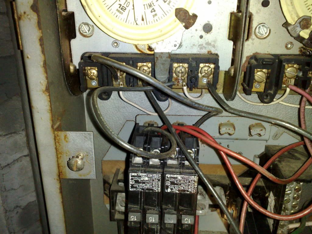
1) By looking at this pic can you tell me if it is 240v or 120v. I read on another forum that by looking at how the timers were hooked up that you could tell. If wires are connected to terminal 1 and 3 then it is 240v.
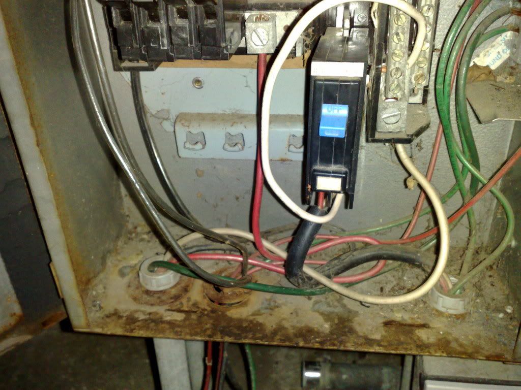
2) The first pic is an image of where i want to install an additional breaker for the heater (my old heater did not require an electrical hookup). I bought a 30amp dual pole breaker, is this the correct one for a Hayward LoNox heater? I bought this since the ones running my pumps are two 15amp breakers hooked up together.
3) The box itself looks pretty bad, should i change it, if so any low cost recommendations.
Any advice is much appreciated
Thanks
The second picture is an image of the breaker box located next to my pool. The lower left is where the main wires come in, I have one black and one red wire that are used to run the pump, there is a white wire that is for the lights and one green wire for grounding.
1) By looking at this pic can you tell me if it is 240v or 120v. I read on another forum that by looking at how the timers were hooked up that you could tell. If wires are connected to terminal 1 and 3 then it is 240v.
2) The first pic is an image of where i want to install an additional breaker for the heater (my old heater did not require an electrical hookup). I bought a 30amp dual pole breaker, is this the correct one for a Hayward LoNox heater? I bought this since the ones running my pumps are two 15amp breakers hooked up together.
3) The box itself looks pretty bad, should i change it, if so any low cost recommendations.
Any advice is much appreciated
Thanks