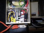
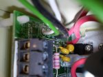
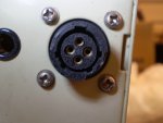
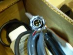
This post inspired me to DIY the power supply, so I'd thought I'd post some tips. I bought a house with an easy touch system, but no chlorinator. The power center has a space for 3 parts, transformer, Rectifier Board, and Cable. The replacement parts for these are almost $500. Instead, I bought just the IC40 and a cheap power supply ($26 shipped) off eBay (AC 110V-220V to DC 36V 400W 11A Switch Power Supply). After installing the chlorinator in the plumbing, I ran the existing wire into the power center. I cut off the connector from the Chlorinator to find 4 wires. Black Ground, Red 36v, White Data+, Green Data-. You can also verify these by testing the cutoff connector and the post above (the plug is mirror of the connector described above) I wired the power supply to the relay for my pump and then Red (36v) and Black (Ground) to the power supply. At this point the chlorinator will light up and work normally. Then I connected the White and Green to the COM port of my easy touch. The com port had existing data+ (Yellow) and data- (Green) wires in them from the pump. I wired in White (Data+) matched with Yellow (data+) on the com port, then green (data-) with green(data-). Now I could see the easy touch communicating with the chlorinator. I can see the salt level and control the output %. Success! Easier then I expected.


")