Solar Panel Layout

tomzo

0
LifeTime Supporter
May 29, 2011
77
Escondido, CA
Greetings,

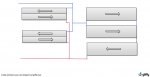
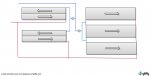
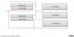
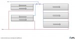
I have some slightly mismatched solar panels and wanted to see if anyone had some ideas on the best way to connect them. After reading a number of posts on the topic I came up with the conceptual layout shown in the attachment. Two of these panels are the ones that have the inlet and outlet on the same header and the other three are one direction flow. I will be adding to this system in the future as my budget allows but for now these are the only panels I have.

I was trying to get the length of inlet piping as close as possible to equal lengths - I am not sure on how important the outlet pipe length is.

Any advice is appreciated!

Thanks
Tom
 

Attachments

  • Panel_Layout-1.jpg
    Panel_Layout-1.jpg
    40.8 KB · Views: 122
You don't want to feed the inlet of the lower panel on the right from the outlet of the other two panels. You lose efficiency trying to heat warmer water. You want the water entering all panels to be pool temperature.

You'd normally have the water flowing through all three headers on the right side panels on both the inlet and outlet side.

With the different flow characteristics, I'd want to plumb the inlets to the different panel types independently so you can use valves to adjust their flow. The panels on the right will produce less back pressure than those on the left.

Your inlet on your right side panels needs to be at the bottom with the outlet at the top to allow them to purge the air when the pump starts sending water to them. Those panels are designed to be mounted with the headers at the top and bottom rather than the end.
 
Your most recent version is starting to look pretty good, but there are some improvements you could make.

Is this going to be installed on a sloped roof? On a sloped roof you need every pipe to go either up or down and not change up/down direction except at the very top of the system. For example your red pipe on the bottom left goes down across and then up (assuming a sloped roof). That is no good as the pipe can't drain if you do that.

On the far right, the three headers are all chained together with the pipe connected on one end. The other side of those three panels should also be done that way with the pipe connecting at the top. That will make the path lengths the same for all three panels.

For the two panels on the left you want to do something related, though it can't be quite the same. The blue pipe should go straight into the panel on top left, not go down and then back up to the panel. Like wise the red pipe should go down to the bottom on the left, not exit at mid-height. There are other ways of getting the same effect, not only the way I describe, so if there are additional constraints not shown in your diagram, there will be some way to do it, though it might not be the one I describe.
 

Enjoying this content?

Support TFP with a donation.

Give Support
Thread Status
Hello , This thread has been inactive for over 60 days. New postings here are unlikely to be seen or responded to by other members. For better visibility, consider Starting A New Thread.