Wiring up a mechanical timer - Electrical help please!

Sep 23, 2009
132
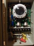
I bought a heavy duty GE mechanical timer and I followed instructions on how to wire it up tonight, but faced issues when I attempted to run the pump (issues = heard some "crackling" and saw some smoke coming from the timer's circuit board... :hammer:). The timer says it's compatible with pretty much all voltages.

So, here's the low down in my pool shed:
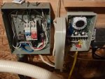
- piggy back fuse panel with 2 20 amp breakers which run the pump, and 2 15 amp breakers which run the pool's lighting and the shed's lighting.

The wiring that went directly from the 2 20 amp breakers in the piggy back box to my pump consisted of 1 black wire, 1 white wire, and a bare copper wire. I assumed this meant I was putting "110" to my pump, and so I followed instructions for wiring the timer to 110. I followed instructions to a tee (it only had about 4 steps, and included pictures...wasn't very tough), but once the pump had run for about 20 seconds, I got the crackling and the smoke ... at which point I quickly flipped the breaker. What gives?
 

Attachments

  • P1020558.JPG
    P1020558.JPG
    58.8 KB · Views: 230
  • P1020559.JPG
    P1020559.JPG
    56 KB · Views: 221
  • P1020560.JPG
    P1020560.JPG
    59.6 KB · Views: 220
Check the required voltage on your pump. Many pumps either require 220/240v or can be selectively set to 220/240v or 120v. If your pump requires 220/240v, both your white and black lines may be hot, with the third wire being the ground, which I assume you joined to your ground source using the wire nut that GE supplies. There are two sets of instructions with pictures included with your switch. The first set is for 120v hookups and the second set is for 220/240 hookups.

There are also two sets of jumper leads supplied with your switch. The larger diameter (smaller gauge #) leads are used for 240v, while only one of the smaller leads is used for 120v. You must also set the four DIP switches to match the voltage required by your pump. The default setting of the GE switch is actually 277v.

I suspect one of two things is going on here: Either the pump needs 220/240v and the switch is jumpered and wired for 120v (this would explain the smoke) or it's wired and jumpered correctly, but the DIP switches are still sitting at the default setting of 277v.

>> UPDATE: Just saw your pictures for the first time. Looks like you've wired and jumpered the switch for 120v. I can't quite see if the DIP switches are all set to the left [ON] or to the right [OFF]. All [ON] would be consistent with your 120v wiring configuration, but you really need to determine if your pump needs 220/240v or 120v as well as what's being supplied from your breaker box via the Romex through the black and white wires.

BTW the ground wires are joined OK, but GE recommends electrical tape around this junction to keep the wire nut in place over time. Don't even know if the Romex you used is adequate for this location, but even if it is, it absolutely must be contained in a conduit with termnation fittings on both the breaker and switch housings. Same goes for the yellow jacketed line between the switch and the pump (on both sides).
 
One thing you need to understand, TWO breakers on one circuit means 220 Volts with each breaker controlling one hot line (could be both black, one black and one other color, or two other colors, or one black and one white. A 110V Circuit will involve ONE breaker controlling one hot line, usually black, and one neutral, usually white. If you wired TWO hots into a 120V timer configuration and let the smoke out, you probably fried something in the timer.

As this thing is more complicated than the truly mechanical Intermatic timers I am used to, I can only suggest you get someone more experienced to diagnose what damage has been done to the timer if this is indeed the case.
 
Durk said:
One thing you need to understand, TWO breakers on one circuit means 220 Volts with each breaker controlling one hot line (could be both black, one black and one other color, or two other colors, or one black and one white. A 110V Circuit will involve ONE breaker controlling one hot line, usually black, and one neutral, usually white. If you wired TWO hots into a 120V timer configuration and let the smoke out, you probably fried something in the timer.

As this thing is more complicated than the truly mechanical Intermatic timers I am used to, I can only suggest you get someone more experienced to diagnose what damage has been done to the timer if this is indeed the case.

Durk is spot on about the breakers. I just couldn't trace the lines coming from your breakers in the picture. If the lines going to the timer switch are coming from the red breakers and the red breakers are bound together, then you've got 220v running to your timer in the form of two 110v hot wires + ground.

I've had Intermatic mechanical timers fry before and the resulting symptom was for the relay to remain closed regardless of the switch position, meaning everything connected to the switched side of the relay was getting power 24/7. Don't know if the GEs fail this way. You can rewire your setup for 220/240v as per the instructions (don't forget to change the DIP switches) and see if the LEDs are operational. Orange LED indicates power to switch - Green LED indicates power to load side of switch (your pump in this case).

Good luck, and don't forget to kill the power to your panel before doing any rewiring. And seriously dude, clean up that romex nightmare. Just looked at the lines feeding your panel and they also need to be housed properly in conduit. If this is an outdoor application I'm also guessing that the romex is not rated for this application, let alone whatever gauge wires are in those jackets being adequate for the amperage of the breakers. You'd get a lot of bang for your buck (not to mention peace of mind) to have an licensed electircian clean this all up at once.
 
After close scrutiny of the wiring (as close as I could get anyway). It does appear that the wiring from the 20 amp breakers is 220 volts feeding the timer. The left hand wire on the top of the breakers appears to be a white wire that's been taped black and it's running to the timer along with the black wire meaning that 240 volts is being supplied to the timer and transversely the pump. While it looks like you have it wired correctly, you most likely have the timer set up incorrectly. You've most likely fried something in the timer but I've seen them work after an incident like that. There's no harm at this point in configuring it correctly and trying it. Any damage has already been done. Bummer about that!
 
Clearly I'm not well versed with electrical matters. I appreciate the help so far. One thing I know to do is always shut off service to whatever I'm working on ... and then check with a voltage tester before I do anything.

24k - An electrician didthis job. lol I'm not sure if it's considered indoor or outdoor, but it's a fully shingled/framed/sided 12x12 shed. The supply to that panel ishoused in conduit, but not all the way up to the panel. Just to about 8 inches from the panel (meaning about the same distance is covered from the ground). As far as I know, that meets code here.

Thankfully, the local Home Depot will be taking this timer back and exchanging it for a new one. I just wanna make sure I wire up the new one correctly.

Yes, you are all correct ... I thought I said it in my OP, but the 2 20 Amp breakers do indeed feed the pump. The reason I got confused was that the wiring only had 1 white, 1 black, and the bare ground. I was under the impression that a 220/240 wire would have another colored wire to make 3 plus the ground. My instructions showed 3 plus a ground in their examples for wiring up 220/240 so I figured that couldn't be what I have. Would this indicate that I just have a "single pole, single throw" set up, with 220/240 Amp service?

Anyway...thanks again! Hopefully we'll get this figured out soon! :)
 
You're right, the electrician should have used different color wires for the 240 volt power but it's not uncommon to use the white wire and tape it as is done there. Since the pump doesn't need 120 volt you don't need the fourth wire so he just used 2w/gnd romex to run power to it.
 
wes8398 said:
Clearly I'm not well versed with electrical matters. I appreciate the help so far. One thing I know to do is always shut off service to whatever I'm working on ... and then check with a voltage tester before I do anything.

24k - An electrician didthis job. lol I'm not sure if it's considered indoor or outdoor, but it's a fully shingled/framed/sided 12x12 shed. The supply to that panel ishoused in conduit, but not all the way up to the panel. Just to about 8 inches from the panel (meaning about the same distance is covered from the ground). As far as I know, that meets code here.

Thankfully, the local Home Depot will be taking this timer back and exchanging it for a new one. I just wanna make sure I wire up the new one correctly.

Yes, you are all correct ... I thought I said it in my OP, but the 2 20 Amp breakers do indeed feed the pump. The reason I got confused was that the wiring only had 1 white, 1 black, and the bare ground. I was under the impression that a 220/240 wire would have another colored wire to make 3 plus the ground. My instructions showed 3 plus a ground in their examples for wiring up 220/240 so I figured that couldn't be what I have. Would this indicate that I just have a "single pole, single throw" set up, with 220/240 Amp service?

Anyway...thanks again! Hopefully we'll get this figured out soon! :)

No worries Wes. Just like to see things buttoned up, whether they're required by code or not. Usually code in the Great White North (my family is from Canada) is stricter than what we get away with here in the States.

I have the same GE Switch running to my pump and salt chlorinator in the 240VAC configuration. The two hot wires from the panel are on each of the "SWITCH" terminals, which are, in turn, jumped to CO and CO2. This gets the juice to both relays. My chlorinator (the pump in your situation) is then wired to NO and NO2, which are connected only when the timer is on. So you've got two poles wired, with two relays switching over when the timer is activated. There is no neutral or common wire in this configuration. These additional wires were added to 220/240v code around here in 1995, but many devices don't use them to remain backwardly compatible with typical legacy house wiring like most of us still have. -24K
 
I exchanged for a new timer today, then came home and hooked it up for the 220/240 voltage and all is well, as far as I can see.
24k - Is yours pretty warm to the touch? I'd had mine running for a few hours before I read your post, then I went back to see if I had it running on the same connections as you do (which I do), and when I went to take the face plate off, it was pretty warm. Just wanted to see if this could be considered 'normal'. Also, are the pairs of live wires (2 from source, 2 from load) interchangeable with regards to which terminal they go to? (reworded: can either live wire from the source go to either of the two "switch" terminals, and can either of the live wires from the load go to either N0 or N02?)
 
wes8398 said:
Also, are the pairs of live wires (2 from source, 2 from load) interchangeable with regards to which terminal they go to? (reworded: can either live wire from the source go to either of the two "switch" terminals, and can either of the live wires from the load go to either N0 or N02?)

Yes, it makes no difference in 220V mode. It might in a 110V set-up. Don't reverse the pairs, however. If both source wires are connected to the load terminals and vice versa, the timer loses power when the pump turns off, and will never turn on again.
 

Enjoying this content?

Support TFP with a donation.

Give Support
Good to hear things are working for you. Durk is on the money again on the interchagability of the lines. 240V devices cycle back and forth between the two 120V lines, so which one hits first is not a big deal. On the other question, yes the switch runs hot, but that shouldn't be a problem if your under the 40AMP, 2HP limits of this unit.

I was a bit hesitant to replace my Intermatic timer switch with the GE unit, as the Intermatic mechanical units are built like tanks, but they also rust easily and I've now seen two of them blow out. In the end the digital settings, the rubber override on/off switch on a plastic background (as opposed to sliding a piece of metal that's within inches of the screwdowns) and the NEMA enclosure sealed the deal for me. Like you, I figure I'm just a trip to Home Depot away from a free replacement if it turns out to be flakey. Enjoy! -24K
 
24k,
in case you weren't aware Intermatic makes outdoor weathertight enclosures for just about all their timers, mechanical or digital. I believe the enclosures may be rated NEMA 4X but not sure on this. If you have the old Intermatic you can get just the enclosure and swap the guts from your old one in. If not you can specify the timer already in the enclosure. I've never seen them at Lowes or HD but they are listed in the Intermatic catalog. You may have to get it online or at your local electrical supply house.
 
ShockerLU3 said:
24k,
in case you weren't aware Intermatic makes outdoor weathertight enclosures for just about all their timers, mechanical or digital. I believe the enclosures may be rated NEMA 4X but not sure on this. If you have the old Intermatic you can get just the enclosure and swap the guts from your old one in. If not you can specify the timer already in the enclosure. I've never seen them at Lowes or HD but they are listed in the Intermatic catalog. You may have to get it online or at your local electrical supply house.

I understand all of the above and have owned two Intermatic T104s and have replaced the guts with the M104 inserts. That doesn't negate the fact that they both fried under different circumstances. I'm not saying the GE won't ever fry, but I'm done with Intermatic, who want 3X the price for their digital versions. I also like the idea of touching plastic vs. metal when working in wet areas like the my pool pump. Lowes carries Intermatic, but Home Depot has dropped them in favor of GE/Jasco.
 
I'm a fan of the T104 and not a fan of anything digital exposed to the weather. Intermatics ARE built like tanks, and what goes is usually the motor, which can be replaced for much less than the mechanism. If they fry, something else probably contributed to the problem (lightning, failing motor causing excess draw, weather infiltration, etc.) Fail a digital, and we're talking new unit. If you are happy with the guarantee life on the digital have fun. I hope GE builds them better than they do their stinking phones. I'm sticking to my T104's. (6 years on my current one, 30 years on my old one, original mechanism, 3 or 4 motors including Hurricane Floyd victim and lightning strike victim.)
 
Thread Status
Hello , This thread has been inactive for over 60 days. New postings here are unlikely to be seen or responded to by other members. For better visibility, consider Starting A New Thread.