Where can I find the wiring diagram for the connection of Whisperflo WFDS-6 (230V) 1.5HP 2 speed Pump and Intermatic PE153 (Digital Timer) for a 2 speed operation. I would appreciate a reply back. Thank you.

Whisperflo WFDS-6 and Intermatic PE153 (Digital Timer)
- Thread starter kevinm2
- Start date
You are using an out of date browser. It may not display this or other websites correctly.
You should upgrade or use an alternative browser.
You should upgrade or use an alternative browser.
Not in the owner's manuals? That's the first place I would look. If you don't have them, you should be able to get them on Pentair's/Intermatic's websites.
I don't have the equipment yet! There is nothing on Pentair's web site for a rookie.
And I have to show it to an electrician.
And I have to show it to an electrician.
The timer side of the wiring is well documented in the Intermatic PE153 manual, while the pump side of the wiring will be shown on a plate attached to the motor. Even a half way competent electrician will be able to do it easily.
Can't find an electrician for the weekend! So I am doing it myself.
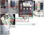
Can I get an experts blessing on the following connection between the Whisperflo WFDS-6, Intermatic PE153 and the Goldline GL-35.
I hope the picture and the diagrams are descriptive enough.
1. Is it OK to use 14AWG wiring?
2. In the pump, should I remove all the connections (The White, Black and Yellow Wires) from the pump to the toggle switch; since the toggle switch will not be used?
Your help is greatly appreciated. Thank you.
Attachments
14 gauge wire will be fine.
Yes, remove all the wires coming from the toggle switch and tape them out of the way somewhere so they won't touch any of the electrical connections.
Your diagram is correct assuming that the solar controller does not turn the pump on/off. Some solar systems are setup to have the solar controller turn the pump on when the solar system wants to run. Others depend on the pump already being on at the right time of day.
Should I disconnect from the toggle and the Terminal side, and take the White, Black and Yellow short wires out of the motor compartment, Or Just disconnect from the Toggle side, tape and leave them there.
It seems they will not be doing anything disconnected from the toggle.
It seems they will not be doing anything disconnected from the toggle.
I would leave the toggle in place, in case you ever want to use it in the future. However, it doesn't really matter and there will be less of a risk of a short if you remove it completely.
Are you sure your diagram wiring works? I tried the same exact this on my Hayward RS1502 with the same timer and nothing happens. The pump does not turn on. Doesn't line 3 and 5 need it's own power source? I am so confused...
b_f thanks for bumping this up again and making me look at it.
You are right, it won't work as shown.
Power comes in on 1 & 2.
Common of motor goes to 1 with power in.
High speed wire on motor goes to 4.
Low speed wire on motor goes to 6.
A jumper goes from 2 to 3.
A jumper goes from 3 to 5.
It will work that way.
To get the solar controller to work.
You need a wire from term 2 on the controller to term 1 on the timer.
You need a jumper from term 5 on the timer to term 7 on the timer.
You need a wire from term 8 on the timer to term 3 on the controller.
I wanted to bump this again and give a shout out to Bama for his last post!
My Father in law and I spent yesterday replacing my single speed pump with a 2 speed pump and replacing my old timer switch with the PE153. Well needless to say we could not get the wiring correct on the PE153. Last night I got the laptop out and started searching on TFP and came across this thread and Bama's post around 3:30 a.m. I was so excited to find the post I wanted to go out to my pool house and re-wire the switch right then and there! But the wife brought me to my senses. So after some sleep (3-4 hours) I went out and re-wired the switch according to Bama's post and BAM the pump fired up on both speeds!!
So again Thanks Bama and Thanks to TFP for such a great site! Now I am off to Walmart for some borax and muriatic acid!!
Happy swimming!! :nemo: :fish:
My Father in law and I spent yesterday replacing my single speed pump with a 2 speed pump and replacing my old timer switch with the PE153. Well needless to say we could not get the wiring correct on the PE153. Last night I got the laptop out and started searching on TFP and came across this thread and Bama's post around 3:30 a.m. I was so excited to find the post I wanted to go out to my pool house and re-wire the switch right then and there! But the wife brought me to my senses. So after some sleep (3-4 hours) I went out and re-wired the switch according to Bama's post and BAM the pump fired up on both speeds!!
So again Thanks Bama and Thanks to TFP for such a great site!
Now I am off to Walmart for some borax and muriatic acid!!Happy swimming!! :nemo: :fish:
I'm glad that post helped you, and it's good to hear people come back and say they used what we've written.
Thread Status
Hello , This thread has been inactive for over 60 days. New postings here are unlikely to be seen or responded to by other members. For better visibility, consider Starting A New Thread.