Solar Panel plumbing....

Last fall we had a freak frost and my Fafco 4x10 panels froze and cracked. I was able to repair most of them using "goof plugs" that I got from a local irrigation shop. I cut the cracked galleries open and glued the plugs in with cyanoacrylite (sp?) and they are solid as a rock but I safety wired them in with stainless wire as well for added assurance.
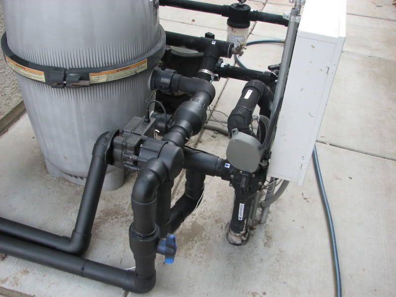
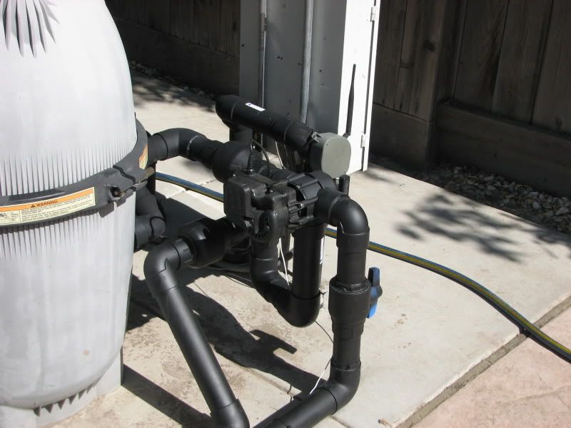
My original install did not include a vacuum relief and my panels remained charged even with the solar off. I would like to change this setup now ( lesson learned) and was reading different threads in the forums with regard to proper install. I'm going to start with installing my vacuum relief at the top of the panel array (I know this is a topic which has varied opinions) as this is where the Fafco installation manual suggests to put it.
I also read that the 3 way valve needs to be "leaky"so that the supply line to the panels will drain when the solar is off and the pump continues to run. Somebody mentioned drilling about a 1/2"hole in the valve and I found somewhere on the internet where the Hayward people suggest removing the internal seal on the valve.
Has anybody have any experience or insight as too which method I should use to accomplish making my valve "leaky"?
 
A check valve on the supply line will prevent the panels from draining on that side of the vacuum release so I wouldn't do that.

The best thing to do is get a three way solar valve which is not all that much more money than a standard 3-way. You will also need a vacuum release valve (VRV) and a check valve for the return side. Isolation ball valves are a nice to have but not necessary.

You can actually put the VRV nearly anywhere from a few feet above the pad on the supply side all the way to the top of the panels but I would not put it on the return line lower than the panels otherwise there is a chance it will leak during priming.
 
Just sharing how my solar system plumbing is; installed professionally by Solaron. It is self draining and has a check valve prior to the 3-way automatic valve (see top pic), and a check valve on the return side(bottom pic). Either way, if solar is off the 3-way valve closes, the supply line is never going to drain fully. The supply line feeds the panels from the bottom. I believe the idea is to ensure the system tubing is not fully filled with water and there is no room for expansion if a freeze occurs, which would cause the tubes to burst. Perhaps I am missing something? My drains with no problem.

IMG_1228.jpg


IMG_1229.jpg
 
Yes putting the valve before the 3-way right after the filter will allow for draining. That is the typical installation. When you said put the check valve on the supply line, it sounded like you meant the line going to the solar after the 3-way which would have prevented draining.
 
uncledeadly said:
...Somebody mentioned drilling about a 1/2"hole in the valve and I found somewhere on the internet where the Hayward people suggest removing the internal seal on the valve.
...

The Heliocol solar manual says 1/8" hole.
 
mas985 said:
A check valve on the supply line will prevent the panels from draining on that side of the vacuum release so I wouldn't do that.

The best thing to do is get a three way solar valve which is not all that much more money than a standard 3-way. You will also need a vacuum release valve (VRV) and a check valve for the return side. Isolation ball valves are a nice to have but not necessary.

The system I currently have is a Goldline digital (don't know if it's a 235 or not) hooked to a Hayward ( I think ) PS 3 way valve so I am not too attentive to spending more money....would just like to get this equipment tailored to the solar. What size hole is best to drill into the valve or is the suggestion of removing the seal from the valve valid?
If the drilled hole is recommended is the placement of the hole crucial? Is the water runiining past the hole creating a vacuum as in jet effect to scavenge the water from the supply side of the solar ?


You can actually put the VRV nearly anywhere from a few feet above the pad on the supply side all the way to the top of the panels but I would not put it on the return line lower than the panels otherwise there is a chance it will leak during priming.

Thanks for your input!!
 
1/8" hole is probably sufficient in the middle of the diverter. It is meant to allow the water to flow out of the supply side pipe when the pump is off. If the valve is turned off for solar while the pump is running, the panels will likely remain filled because the pump is still providing pressure to the panels. They will only drain once the pump is shut off.

If the valve is in the off position and the pump is turned on, water will very slowly fill the supply pipe and panels but the flow rate through the panels will be limited by the tiny hole so not much water will flow when the valve is in the off position but some does. A true solar valve does not allow any water through the panels when in the off position nor does it allow the panels to fill.
 
Thread Status
Hello , This thread has been inactive for over 60 days. New postings here are unlikely to be seen or responded to by other members. For better visibility, consider Starting A New Thread.