Where is Aquarite Flow Sensor?

May 14, 2009
49
Rocket Town, AL
Hi all,
Getting a "No Flow" message on my generator. It's obvious that I'm getting great flow through the system.

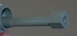
Wondering if my sensor could have some trash on it? Is the sensor mounted inside the cell area, or in-line heading to the cell? Any way to identify from the back of the sensor? I have two sensors mounted in-line, both wires run to the controller, but no idea which, if either, is the flow sensor for the SWG.

Thanks,
:goodjob:
 
The two sensors should be your temperature and flow sensors. The temp sensor is held in place with a clamp, saddling the pipe. The flow switch is threaded into a "Tee" fitting and has an octagonal profile from the outside. If you remove it, you'll need teflon tape or pipe dope when you put it back, and be sure to align the switch properly (there are arrows molded on top of it to show you the direction of flow).
 
All I have is one wire going to a sensor in the t- fitting. According to my manual this is a flow sensor. When I disconnect it, I still see the temp displaying a temp. and the flow sensor light comes on. I can only assume that the temp sensor is built into the chlorine cell. Hope this helps..
 
Brentr said:
All I have is one wire going to a sensor in the t- fitting. According to my manual this is a flow sensor. When I disconnect it, I still see the temp displaying a temp. and the flow sensor light comes on. I can only assume that the temp sensor is built into the chlorine cell.
I have the Aqua Rite T-Cell 15 connected to a Goldline PS-8 controller. The flow sensor on my system is plumbed into the post-filter return pipe before the cell. The visible portion is octagonal shaped, just as sphishex described. The separate temp sensor, held in place with a strap and metal band was placed between pump and filter. The controller reports "pool" temperature (from the individual sensor just before the filter) and "cell" tempertature separately, so there must be feedback coming from another temp sensor in the cell, as Brent suggested.
 
spishex said:
The flow switch is threaded into a "Tee" fitting and has an octagonal profile from the outside.

Bingo! This describes what I see perfectly! Off to pull it out and see what's up! Thanks!

I guess I should have asked this previously, but is it even possible to have a flow switch signal interupted (NO FLOW) due to trash collecting against the sensor? I realize this location is post-filter, but hoping for the "easy fix".

:cheers:
 
The flow switch is simply a micro switch. Its detecting an open circuit or closed circuit. You can verify if your flow switch is working or if its your control box/circuit board.
Check your flow switch wires also. You may have a nick or cut on one of the two wires, which will show as a no flow condition.

TURN THE POWER OFF!!!
If you trace the flow switch wires to the control box, remove them and replace with a short jumper wire across the same terminals the flow switch was connected to.
Turn the system back on. If the unit now shows proper operation, it's not your control box because you've just simulated a good flow condition.
With the system still running, put a multimeter on continuity and check the two flow switch wires. With proper flow to activate the flow switch, you should see a closed circuit condition.

Finally, turn the pump off and remove the flow switch. This should look like a gray body with a long center post and a stainless steel paddle with a magnetic disk glued to it. If the magnet fell off, no flow.
Or the flow switch may look like a hinged paddle, without the center post. In either case, when the water flow hits the paddle, it moves it to activate the micro switch. Put your multimeter probes on the flow switch wires and move the paddle by hand to simulate good flow, and check for continuity.
If everything checks out, time to look at your plumbing for something blocking flow.
 
Flow switches can malfunction in a variety of ways. Yes, it is possible for some bit of debris to get stuck in the switch and jam it either open or closed. That isn't the most likely possibility, but it certainly is one of the plausible possiblities.
 
Thanks for all the help gang! I went ahead and pulled the switch (out of curiosity as much as anything)...here's what I'm looking at. I get the feeling that the hole in the end of the sensor isn't there to save weight! :grrrr:
 

Attachments

  • DSC_7289b.JPG
    DSC_7289b.JPG
    21.1 KB · Views: 181
Here's what it should look like:

q12DSMSC.jpg


The metal part that opens/closes the circuit is MIA on yours. You'll need to replace the switch.
 

Enjoying this content?

Support TFP with a donation.

Give Support
I guess it would be obvious to someone who has looked at this kind of flow switch before. I would not fall into that category.

The sensor is located up-stream of the cell. I do not add any chlorine to the pool in any way, just the SWG.

Again, thanks for your help gang.

:cheers:
 
Welcome to TFP!!

Warning!!!


It is VERY easy to crack the Tee that the sensor goes in! Please read Tim's advice here on using Teflon and only tighten it hand tight at first. If it leaks when hand tight, remove it and take off all the old Teflon, retape it and reinstall it. I'm just trying to save you a potentailly huge headache :cool:
 
Thread Status
Hello , This thread has been inactive for over 60 days. New postings here are unlikely to be seen or responded to by other members. For better visibility, consider Starting A New Thread.