Intermatic T104

griego

0
Nov 9, 2018
34
Miami
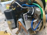
Hello, I bought a new house and my pump seems like is not working. I had the wh40 intermatic installed, and purchased the Intermatic T104 208-277-Volt . Now looking at the connection cables for 220v timer the previous one was connected in a weird way. unnamed.jpg
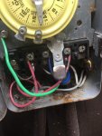
From the power box theres a 3rd cable which is silver that is not going to ground. Also from the pump there is white cable that is not going to load no4 position and is connected to the silver one from the power box. Any ideas? It should be from power 1 to 3 and ground, and from the pump to 2 to 4 and ground as per wiring instructions.

Thank you, electrical is not my main thing! I wanted to be sure before I connect the new timer.
 
Is there any chance your pump runs on 120V? The silver wire might be a neutral, with the 2 red hot wires (240V across them) running the clock motor on the line side, and the unswitched neutral and one of the switched load outputs (120V between those) running the pump.

I'd check the pump's label and wiring (some pumps can be connected to either 120V or 240V depending by connecting to certain terminal combinations). I'd also measure the voltage across all combinations of the line power wires (red to red and each red to silver) and from each of those wires to ground. If it is a 120V pump, connecting the new timer the same way would be okay (it's okay to switch just the hot side of a 120V circuit but 240V must be switched on both legs).
 
Welcome to TFP.

Please Read This BEFORE You Post and put details about your pool and equipment in your signature. We need to know what pump you have and if it is 120v or 220v.
 
Thanks for the earlier comments.

Here are my answers/findings:

1- Power between cables
R to ground 112v each red cable

R to R cant get a measurement

R to silver 120 each each red cable

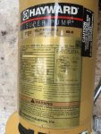
2- Picture of the pump , seems it can handle both 120v or 240v, but setup for 240v
IMG_6647.jpgIMG_6648.jpg

I bought the t104 to replace the wh40 thinking they are the same in terms of voltage and features.

3- From jmastron comment "If it is a 120V pump, connecting the new timer the same way would be okay (it's okay to switch just the hot side of a 120V circuit but 240V must be switched on both legs)."

Weird part it seems my pump is setup for 240v at the moment. Any idea? I can get an electrician to do it, but they charge at least $100 and thought this was an easy switch of a timer reading online.

Thank you for the comments.
 
Even if pump is 220v you still only have to break one line and not both.

Both lines on a 220V circuit are hot and code requires they both be switched off at the same time. You do not want the pump off and someone handling a hot wire.
 
There are 220v timers on the market that only break one hot. Besides not sure I understand what you mean by handling a hot wire. Aren't we talking about an installed pump that just needs a new timer. Once the timer is in place the circuit breaker gets put back on what difference does it make whether one hot or both are being interrupted. If there's no danger while the pump is on and all grounds are connected so then breaking one hot to interrupt the the pump should not be any more dangerous. I guess maybe it's just code but nothing else I can see.
 
There are 220v timers on the market that only break one hot. Besides not sure I understand what you mean by handling a hot wire. Aren't we talking about an installed pump that just needs a new timer. Once the timer is in place the circuit breaker gets put back on what difference does it make whether one hot or both are being interrupted. If there's no danger while the pump is on and all grounds are connected so then breaking one hot to interrupt the the pump should not be any more dangerous. I guess maybe it's just code but nothing else I can see.

The danger is to anyone working on the pump who assumes the off switch is wired to NEC code.

NEC code section 430 specifically addresses switches controlling motors.

If you do not clearly understand what you are doing we recommend you get a licensed electrician. We see many examples of unsafe DIY electrical work around pool equipment.
 

Enjoying this content?

Support TFP with a donation.

Give Support
1) I agree with JamesW that the pump is likely set to 120V. For a paranoia check, measure the voltage right on those wires right at the pump. If it is indeed 120V, you should be able to wire the new timer exactly the same way as the old.

2) This doesn't appear to apply to the OP, but agree that 240V pumps absolutely should be switched on both legs, and I believe that is required by code. I've found references to old baseboard electric heaters perhaps being allowed to switch just one leg, but it seems incredibly dangerous to do that especially for an outside pump with separately accessible wires etc. When you switch the hot leg of a 120V circuit, the unswitched wire is at 0V relative to ground, but when you switch just one leg of a 240V circuit, the unswitched wire is 120V to ground.
 
Jmastron, thanks for the input. What do you mean by switched?

Yes, my pump is at 120v today I measured it.

Switched in this case means controlled by the T104. If it were a 240V pump wired in accordance with the wiring diagram that came with the timer, both wires (which are both considered "hot") going from the timer to the pump would be disconnected when the timer is off. In your case, only one wire going from the timer to the pump is disconnected when "off", the other is always connected to the neutral. This is normal/acceptable for a 120V circuit, as the neutral is nominally at 0V relative to ground. Thus, leaving the wiring as-is is correct for a 120V pump. You can't change the timer inputs, because the timer itself is using 240V.

I do wonder why that was done, because typically if you have 240V available that would be used -- a 240V circuit actually has half the current, and thus doesn't require as large of a wire, for a given wattage. I'm guessing either an old pump was 120V-only, the old timer's other output switch stopped working, or something else. Is there anything else switched by the pump wire (a relay for something, an SWCG or Stenner pump, etc)? You could consider changing the pump-side wiring to 240V (and then wiring the timer per the diagram), but you want to be really really certain before messing with it more.
 
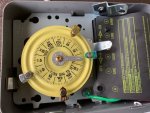
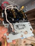
I went ahead and installed it and pump is running with no issues. Though I dont get to hear the clock ticking. I just realized I bought the T104-20 timer which is for 240v. I need to purchase the 120v timer which is T101. Where also the previous owner had a wh40 timer which is also a 240v and I thought it was damaged, because the timer didnt work. Now it all makes sense.. Bummer .. . No, nothing else is switched by the pump. Thanks "jmastron" for your input

IMG_6687.jpgIMG_66881.jpg
 
Ahah -- I missed a big clue you posted before: "R to R cant get a measurement". That means both hot legs are connected to the same leg of the house power and don't have 240V between them.

Basically, for most houses the transformer at the street drops the voltage to 240V with a center tap -- that center tap is grounded and becomes the neutral. In the breaker box, 120V circuits are connected to one of the hot legs (usually divided evenly among the circuits) and the neutral, while 240V circuits require a double breaker that connects to both of the hot legs.

Definitely get a picture at the breaker box; take the cover off too for a view of the wires if you're comfortable doing that. I suspect at some point a breaker failed, or they needed space so they removed a double breaker, or someone just miswired it. Their solution was to reconnect the pump for 120V and probably just to use the switch on the timer manually. I'm concerned about the wiring -- a pump that draws, say, 8 amps at 240V ould be okay with a (dual) 15 Amp circuit breaker and 14 gauge wire, but at 120V it would draw 16 and would NOT be safe with a (single) 15A breaker and the same 14 gauge wire. The installation manual for a new 1 HP Hayward Superpump calls for at least a 10 Amp breaker and 14 gauge wire at 240V, and at least a 20 Amp breaker and 12 gauge wire at 120V -- so if it or a predecessor was originally installed as a 240V pump it may or may not be okay.

If it's 12 gauge wire and a 20 Amp breaker, then you could indeed get a 120V timer (would have to change the wiring so the timer also gets the neutral as one of the line inputs). If it's not, then the safe and right thing to do is fix whatever's going on at the breaker panel to get 240V again, change the pump connection to 240V and change the wiring at the timer.

Let us know; I'm intrigued now to get to the bottom of this!
 
Here is the breaker box. When i switched the breaker to the left the pump wasn't working. Though is weird it has a black/red wires and by the timer I get red/red coming out. I had a similar issue with sprinklers and they needed to buy a dual breaker which separates the 2 lines which is the one to the right.

Is is as simple as getting a 120v timer to make it work here? [ (would have to change the wiring so the timer also gets the neutral as one of the line inputs).- how do you do that? Am i losing any benefits of not working the pump at 240v? Thank you

https://www.dropbox.com/s/hjnm84ynyq79zj9/IMG_6707.jpg?dl=0

https://www.dropbox.com/s/hir9w46bt0h0q6z/IMG_6708.jpg?dl=0
 
Ok, the subpanel box has 5 slots. Regular 120 volt breakers take up 1 slot. 240 breakers take up 2 slots.

Tandem breakers take up 1 slot but give you (2) 120 volt wires. So, a tandem breaker is basically (2) 120 volt breakers in 1 slot.

You have 3 tandem 120 volt breakers and (1) 240 volt breaker.

What does the 50 amp 240 breaker go to?

With 3 tandem 120 volt breakers, you can power (6) separate 120 volt devices.

To use the pump at 240 volts, you would need to remove 2 tandem breakers to free up 2 slots to install a 240 volt gfci breaker.

But, then you would have only (2) 120 volt breakers on the remaining tandem breaker. That might work depending on what you need to power at 120 volts.

Note that the ground and neutrals are combined. That's incorrect for a subpanel.

In a subpanel, the ground and neutrals have to be separated. The neutrals need to be isolated from the box.

Ground and neutral only connect at the service entrance.

I recommend that you get an electrician to make sure that everything is wired correctly and change the pump to 240 volts.

Can you list everything being powered by the subpanel?
 
All those 20 amp breakers in the box look like single pole breakers to be used on 120V circuits.

It looks like they made your pump 120V so that they could fit six 120V circuits and one 240V into an existing subpanel. As JamesW suggested best to have an electrician in to review the setup and maybe replace the subpanel so it can have two 240V and at least five 120V circuits.
 
Honestly, out of the four breakers starting from the left, the first is the pool timer, and the one all the way to the right is for the sprinklers. I have no idea what the second or the third 240v are for. I just bought the house and trying to figure things out. I dont have any other component that needs heavy power. Might have to get an electrician as sounds like I need some advanced skills here.

https://www.dropbox.com/s/q6uz28jervqeifu/IMG_6709.jpg?dl=0
 

Enjoying this content?

Support TFP with a donation.

Give Support
Thread Status
Hello , This thread has been inactive for over 60 days. New postings here are unlikely to be seen or responded to by other members. For better visibility, consider Starting A New Thread.