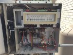
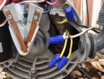
Anyone familiar with A.O. Smith Dual speed pump B2982

Mar 11, 2018
5
Plano, TX
A.O. Smith 1 HP Energy Efficient Dual Spd. Motor - Full Rate (B982, B2982)

We recently upgrade our original single speed pump to the dual speed pump above. It seems like our pool control unit was wired to support dual speed but this whole time the previous owner has been using single speed. So we decided to upgrade to dual speed. Upon installation, the pump seems to be running on low which does not create enough suction to prime. While we installed, we accidentally burnt the label of the wires, so maybe we did not connect correctly. Either way, we are not sure how to switch the pump to high speed, we have a toggle switch that we bought, maybe don't even need to buy it.
but not sure how to wire that onto the pump either...
please help.
 
0322,

Welcome to TFP... A great place to find the answers to all of your "speedy" questions... :shark:

Please let us know what kind of automation or pool control system you have.

If the control system can switch between high speed and low speed, than you do not need the switch.

Who installed the pump?

Thanks,

Jim R.

Hello Jim:

My husband installed it. here are some pictures if it helps:

IMG_2736.jpgIMG_2737.jpg
 
Here is a brief breakdown:
the control box seems to be wired for a dual speed motor, we did not change any existing wiring when we installed the pump.
the original pump was single speed. if you see the wiring going to motor there is a black, white, blue and green.
I suspect the blue is for the dual speed but haven't tried it yet as I cannot get it to run at high speed.
it seems to be running on low even though there is 240V going to the motor.
coming from the motor is a yellow with black stripe and then 2 straight yellows, as well as a white.
right now I have black to yellow with black stripe and white to white.
now what is interesting is that if you look at the control box the main white coming in has black tape wrapped around it. not sure what that means.
at this point, I have tried various wiring combinations but I am afraid of frying something!!
so I am open to suggestions.
 
0322,

To have a two speed pump work, you need three wires coming from your Jandy system.. One wire goes to the common connection in the pump and it will have one leg of the 220 volts needed to run the pump.. One of the other two wires has the other leg of the 220 volts when in low speed and the other wire will have the other leg of the 220 volts when in high speed.

No matter what, for the Jandy system to control both speeds, you need 3 wires and that does not include the green ground wire. Based upon your post above the three hot wires are black white and blue. One of them will be hot all the time, and one will only be hot when in High speed and one will only be hot in Low speed.

To test which wire is which you will have to disconnect the wires from the pump!!

Where is the connector block where the wires are supposed to connect???

I've got an Expert that knows everything, I'll give him a shout.

Thanks,

Jim R.
 
1. Turn off power.
IMPORTANT: TURN OFF ALL POWER AT THE BREAKERS BEFORE PROCEEDING.
2. Mount relay.
The Two-speed Relay must be mounted in one of the four positions on the lower step of the relay compartment in the AquaLink Power Center. If necessary, remove a relay from the bottom step and re-install it on the top step to make room for the Two-speed Relay. Mount the relay using one screw as shown in the diagram above.
3. Wire relay.
Using high voltage wire, connect the normally open (NO) wire from the Two-speed Relay to the low speed terminal on the filter pump. Connect the normally closed (NC) wire from the Two-speed relay to the high speed terminal on the filter pump. Connect the common (C) wire to a Load terminal on a standard Jandy relay, and connect the other Load on that standard relay to the common terminal on the filter pump. Connect the Line terminals of the standard relay to 240 VAC power. Connect the coil connectors of the Two-speed Relay to the Aux. 2 socket on the Power Center P.C. Board (see wiring diagram on Power Center door and in Installation Manual).
4. Turn on DIP Switch #2.
For the system to recognize that it is connected to a two-speed pump, you must move DIP Switch #2
on the Power Center Dip Switches to the ON position.
5. Test system; program Controller.
Check your wiring, then turn power back on. The module may be tested by using the Service Mode button on the Power Center, but note that this mode allows only on/off switching. The two speed function is only available through the Controller or a Spa Side Switch. See main Owner's Manual, and follow the directions under "Label Auxiliaries" on page 8.

So, verify the wiring coming from the box to the pump according to the above. Make sure that you have the two speed relay and that it's wired correctly.

That will tell you which wires are which.

Then, there should be a label on the pump showing the wiring diagram.

Where did the terminal connection board go?

The connection board has the numbered terminals that match the wiring diagram.
 
Hi Jim and James,

This is 0322's husband (uh, Mr. 0322 I guess?) jumping in. Apologies for the delay in replying but I wanted to do some investigating in the daylight before I got back to you and, you know, life ;). So here's where I'm at: the filter is currently running in low speed with a PSI of about 4-5 out of 10 PSI normally (which is what I would expect) and I currently have white (control box) connected to white (motor) and black (control box) to yellow/black (motor). I can switch between the spa and the pool, use Service Mode in the control box and the controller inside the house to switch to low speed, etc. So everything seems to be working fine except for the actual speed of the motor (which is REALLY fortunate given that here in Dallas the weather thinks it's Chicago all of a sudden).

Anyhow, I'm currently seeing two issues:

1. Power from the control box to the motor: I checked all four wires coming from the control box (white, black, blue, and green) and of those only white and black have a charge (110V each). In looking at the control box I see that the blue wire is connected to two red wires, as you can see front and center in this pic.
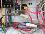
IMG_0158.jpg
One of those red wires goes off to an (unused) oxidizer and the other goes up to a relay you can see in the pic. Coming out of that relay in addition to that red wire (which is attached to terminal "2-NC") there is another red wire (attached to terminal C-4) that doesn't attach to anything else (you can see the yellow end of it in the pic). So my guess is that either that red wire with the yellow end is supposed to be connected to some source of power other there is some other connection that is missing. Either way, obviously the blue wire has no source of power attached to it and consequently only the white and black coming from the control box have any charge.

2. The connections at the motor itself: As for the connector block you've asked about earlier, the first time I attempted to wire up the motor I must have guessed incorrectly with some of the wires as there was an arc and the connector block was, um, melted. A bit.
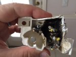
IMG_0157.jpg
So I "surgically" removed it (in retrospect a REALLY dumb move) and tried to figure out which wires from the motor connected to which from the control box. Unfortunately every source I look at seems to have a different configuration, such as the wiring diagram on the motor itself (which naturally doesn't include the actual colors of the wires)
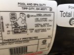
IMG_0155.jpg
and the toggle switch add-on we got in case we couldn't wire up the dual speed from the control box.
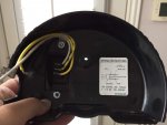
IMG_0159.jpg
Basically, here's what I've come up by trying to perform some type of forensic investigation of the connector block and looking at the other info:

- White from the control box to white from the motor is L2 (common)
- Black from the control box to yellow w/black from the motor is L1 (high)
- Blue from the control box to yellow from the motor is A (low)
- Yellow from the motor is also L2
- Green from the control box is ground

Does it sounds as though I'm on the right track with this? Obviously after my previous melt-down I'm a little hesitant to start randomly experimenting with different wiring combinations. The thing that doesn't make sense, then, is that if white is common and black to yellow w/black is correct, then the motor should be running on high right now, which it clearly isn't. Anyhow, I would greatly appreciate any help I can get. Thanks!
 

Enjoying this content?

Support TFP with a donation.

Give Support
Goof,

I have no way to know for sure, but I believe you only have one error in your wiring...

You say that the motor only runs at low speed.. Since you have the black wire from your automation connected to the yellow/black from the pump and the pump is running at low speed, then that means the yellow/black wire should be your low speed input or "A"...

I would swap the yellow attached to "A" (Lo) with the yellow/black attached to "L1" (High).. Assuming you have not already let all the smoke out of your pump, then the pump should run at high speed... "If" that works, then we can work on getting your automation to switch between high and lo speed.

Keep in mind I have no clue where the yellow and yellow/black wires went before surgery, but based upon your post, that is how I would wire it up..

Just to make sure you understand... The common should get 120 volts all the time (Half of the 220 needed to run the pump.) The High (L1) only gets 120 volts when you want to run at high speed and the "A" (Lo) terminal only gets 120 volts when you want to run at low speed.. NEVER connect both the high and low terminals to 120 volts at the same time..

I'll say a prayer... :rolleyes:

Jim R.
 
Thanks for your kind-ish replies ;). As far as swapping the yellow with the yellow w/black, the problem is that there are 2 yellows, both seeming to head off to the same black hole inside the motor (as you can see in one of the pics in our original post), and I really have no idea which was originally attached to L2 and which was attached to A (in this case I suppose we sent the patients down to the morgue without attaching the toe tags first). So in an effort to minimize the body count further I'll try giving Century a call and see if they can help me diffuse this bomb ("Cut the blue wire. No wait! Cut the red wire... I think" (really mixing metaphors here but they're all just so appropriate)). Thanks!

-Whatevernamewe'regoingbynow
 
whatever,

Calling Century is a good idea... Based upon past experience in manufacturing, when two wires have the same color it generally means they are interchangeable. That is why I suspect that the yellow/black is marked differently.. It is not the same as the two solid yellow ones.

Please let us know the final outcome as we are all hanging on with bated breath... :p

Thanks,

Jim R.
 
Aaaaaaaaand... (dramatic pause) yeah. Well I called the manufacturer (A.O. Smith) and (this is great) it turns out that the number listed online to call for help is actually for the water heater division of the company. So they gave me another number for motors (Regal) which then gave me another number (seriously) who finally told me... (another dramatic pause) they only talk to the distributors. SO then I called the distributor (the website we ordered the pump through) and then I talked to their Tech Support they told me... (yet another dramatic pause) they're just a shipping depot and that I should talk to... (somehow still another dramatic pause) you guessed it: the manufacturer. Haha. So I figured screw it and just went ahead and tried connecting the yellow wires from the motor to the black from the control box and here's what I found: turns out they are NOT interchangeable, as one makes the pump run the same as the yellow w/black wire and the other just makes the pump hum but not actually DO anything. So I'm wondering if we have the white and black wires from the control box switched. If you look at the first pic in the first post above the "white" going to the motor is the 3rd one from the left in the row of black wires going into that leftmost terminal, except that the "white" wire is covered with electrical tape. Actually, the more I try to figure out what's going on with the wiring in the control box the more I'm convinced that whichever of the previous owners had the pool installed had the work done by their cousin who just wired that up real quick with whatever he had lying around for a 6-pack of beer. Really bad beer. Probably whatever the owner had lying around :p. Anyhow, thoughts? Thanks
 
Calling is a waste of time. People who answer the phones don't know the correct information.

To get the right answer, you need to email regal beloit.

Give the pump model number and explain the terminal board was removed and that there are 4 wires and you need to know how to wire without the connection board.
 
Thread Status
Hello , This thread has been inactive for over 60 days. New postings here are unlikely to be seen or responded to by other members. For better visibility, consider Starting A New Thread.