Possible solar plumbing problem?

robrinker

0
LifeTime Supporter
Aug 2, 2007
178
Northeastern Ohio
I originally posted this as an addition to this thread: solar-panel-and-rack-design-help-t12214.html

I need help from the plumbing/hydraulics experts, so I decided to split it off to a new topic.

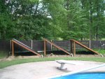
I recently added (12) 2x10 Sungrabber solar panels to my system, mounted across (3) racks. The racks are ~60' from my pump, so there's 60' of 2" pipe there, and 60' back.

[attachment=0:35pf4jzk]racks_pipe.jpg[/attachment:35pf4jzk]

My filter pressure increased by 8psi after the install. The pressure increases by another 2psi when I divert all of the water to the panels.

When I sent water to the panels, the front 2 panels (the one in the middle, and to the right in the picture), cooled down and I felt warm water coming from the returns. The panel to the left stayed hot. I closed the valve going to the right panel, and heard the left panel fill with water and felt it cool down. I opened the valve about halfway on the right panel and it cooled down a bit, but still felt warm to the touch. The panel on the left went from cold to lukewarm. I measured the pipes for all three racks from where they split off of the common send pipe until the rejoin the common return pipe. The left rack has 26' of pipe, the middle rack has 24', and the right rack has 26', so the water shouldn't really favor one rack over the others, right?

Any I ideas what the problem might be, or a solution? I'm thinking it's not the best solution to damper the valve at the right rack, because then it's not getting full flow. Is this line of thinking correct? Is my pump not strong enough? I've always thought 1.5hp was plenty of power. How can I tell if this is a fully rated 1.5hp pump?

The label on my pump has the following info:

Century 1081 Pool Pump Duty
Part #: 8-168099-02 - FR M 56J - Type CX
HP 1.5 - RPM 3450 - HZ 60
PH 1 - SF 1.00 - Volts 230/115 - Amps 7.2/14.4
Time Cont - AMB 40* C - Insul Class B - ENCL DP
Code E - Thermally Protected KA - Form K JM - Serial BD4

Thanks for reading this long post!
 

Attachments

  • racks_pipe.jpg
    racks_pipe.jpg
    159.4 KB · Views: 415
does your plumbing look like A or B?

000_0013.jpg
 
robrinker said:
When I sent water to the panels, the front 2 panels (the one in the middle, and to the right in the picture), cooled down and I felt warm water coming from the returns. The panel to the left stayed hot. I closed the valve going to the right panel, and heard the left panel fill with water and felt it cool down. I opened the valve about halfway on the right panel and it cooled down a bit, but still felt warm to the touch. The panel on the left went from cold to lukewarm. I measured the pipes for all three racks from where they split off of the common send pipe until the rejoin the common return pipe. The left rack has 26' of pipe, the middle rack has 24', and the right rack has 26', so the water shouldn't really favor one rack over the others, right?

You need to include the fittings as well. Each 90 will add about 12' of 2" pipe. A diagram of the exact plumbing might help.


Any I ideas what the problem might be, or a solution? I'm thinking it's not the best solution to damper the valve at the right rack, because then it's not getting full flow. Is this line of thinking correct? Is my pump not strong enough? I've always thought 1.5hp was plenty of power. How can I tell if this is a fully rated 1.5hp pump?

Based on the SF (service factor), it appears to be an uprated pump.
 
My plumbing is like diagram B. Here is an exact diagram of the way it's laid out, doing my best to show 3D plumbing in 2D.

[attachment=0:5pht6xae]solar diagram.jpg[/attachment:5pht6xae]

If exact pipe lengths are needed, I can provide those as well.

Thanks!
 

Attachments

  • solar diagram.jpg
    solar diagram.jpg
    101.9 KB · Views: 367
You want the water to flow across the panel and also flow across the rack.I'll admit I was sure that was the problem here (fig A), but,
I don't see a problem with your plumbing except for, and i don't even know if it makes a difference, the return on rack one follows the rack down instead of dropping straight down to ground level like the other two do.

You said that the pressure increased by 8# after install then 2# more with solar on.
Were you saying that the pressure went up 8# after install with with solar off? Then rose 2# from that when you turned it on?
 
To clarify, the pipe on the middle rack follows the rack down about halfway (it's a 90* on the drawing, but I marked it as 45*), it doesn't drop straight down. You can see this if you look carefully at the pic of the rack I attached in the first post, the pipe is in the shadows under the middle of the middle rack. I did this on both of the racks that needed to meet up with the front rack because I assumed a 45* would offer less resistance than dropping straight down and then taking a 90* turn, and would require less feet of pipe. I know next to nothing about plumbing or hydraulics, but I've read a ton here and from what I read that seemed like the right thing to do.

Pool Clown said:
You said that the pressure increased by 8# after install then 2# more with solar on. Were you saying that the pressure went up 8# after install with with solar off? Then rose 2# from that when you turned it on?

Correct. Before I installed the solar panels and all the extra piping, my filter pressure was 12psi. After the install, with the solar off, pressure is 20psi. When I send all of the water to the solar, psi goes to 22.

I'm not sure if it makes a difference, but I just used a regular ball valve (the red guy in the pic below) and not a 3 way.

[attachment=0:1hd51kfb]valve.jpg[/attachment:1hd51kfb]
 

Attachments

  • valve.jpg
    valve.jpg
    82.2 KB · Views: 354
It's just a bit excessive, the pressure.

I keep thinking there is something there with the pressure going up so much with solar off. How much more plumbing did you have to add to the solar "off" line? Maybe back up a bit and show us more of the plumbing.
 
The plumbing from the last pic is indoors. My racks are about 60' from my pump. That's the only place in my yard that gets enough sun during the day (I have a ton of trees). So I ran 60' from the pump to the racks, 60' back, and about 80' to connect all the racks together. 200' of 2" PVC total.
 
It would be nice if you had a before pic of the piping too. Can you give us a list of all the piping items you added. That valve doesn't look like a full port so it would add some restriction. Since you only increase 2 PSI when you put the solar in the loop, your restriction is before that. IMHO you're going to have to get that straightened out before you can balance the panel flows.
 

Enjoying this content?

Support TFP with a donation.

Give Support
My experience has been that a lot of the ball valves like you used have a smaller port than the pipe diameter, which adds flow restriction even when the valve is fully open.

If you can look at another valve like it and see if there is a full path, that might point to a problem.
 
Also, are those spring check valves (axial plug) you are using or swing check (flapper type). Spring check valves tend to have a lot more head loss than the swing check type.
 
With the solar off (and let me know if I'm correct) the water flows out of the filter, through the check valve, through the ball valve, then continues back to the pool. Before the solar did the water just flow out of the filter, through the pipe and to the pool, with no valves or check valves?

I'm almost positive the check valves used are the spring type because I used two that look exactly the same. My PSI only increased by 2 with the check valve and a 1HP pump. The ball valve shouldn't be causing much of a PSI increase either. On my system the water actually has to flow through a 1.5" ball valve and I don't think that caused my PSI to rise at all.

I think once you figure out why the PSI went up by 8 with the solar off, you may be on your way to figuring out your solar panel problems. Did the flow decrease from the returns with the new plumbing(with solar off)?

Adam

Adam
 
Here is the plumbing from a wider angle. Unfortunately, I don't have a before pic. After cutting the old pipes out, it occurred to me that I should have taken one. Too late now!

The ball valve is the one supplied with the SunGrabber P/N 267 System Kit. I'm not sure if it has a full path or not; short of cutting it out to look at it.

The piping items I added are: 4 90* elbows, two "T"s (and the stuff to the right of the "T"s, obviously), the check valve, and the ball valve. The ball valve right off of the filter is existing. As you can see from the pic, I took the top off of the filter and rotated it from 5:00 to about 3:00 to make this new plumbing fit. That's should not have made a difference, right?

I did notice that as soon as I had the plumbing to the solar panels connected, even with the bypass ball set to "solar off", the solar panels still filled up with water (and informed me that I didn't tighten the hose clamps on my rubber couplers enough). I assumed that was normal, as the water would want to fill up the empty pipe and then would just bypass the panels.

[attachment=0:2wu4ps6x]plumbing.jpg[/attachment:2wu4ps6x]
 

Attachments

  • plumbing.jpg
    plumbing.jpg
    122.5 KB · Views: 252
I wondered if turning the top would have any effect on the pressure. I downloaded the manual and upon looking at it I don't see how that would cause increased pressure. Of course, something could have gotten out of place during the change and cause a problem so I'd check it if I were you.

From looking at the piping, My first suspect would be the check valve. There could be something stuck in it causing high back pressure. You did clean and ream all the piping as you were installing it didn't you?
 
How would I check the check valve with it being glued in where it is?

When I installed the PVC I wiped where I was going to glue with a damp cloth, let it dry, and then sanded it lightly. After that I put the purple primer on, let that dry for about a minute and then applied the PVC cement. This was my first attempt at doing my own PVC so I'm not familiar with all of the exact terminology.

Right about now, I'm wishing I had used a union ball valve for the Solar on/off :-/
 
How would I check the check valve with it being glued in where it is?
The top valve has a union and the solar lines have unions in them. All you need to do is cut the horizontal line running along the bottom of the photo and you can take the entire piece out. I'd install a union at the cut when I put it back together. The frist thing I'd do after getting it out is to shake it and see if the check valve rattles.

Then I would check the filter to make sure it wasn't the problem by concocting a way to hook a backwash hose where the valve was hooked to the top of the filter.

Then hook the filter discharge valve (top) back up with the piping at an angle and close the solar bypass valve and use union half to hook the solar feed to a backwash hose.

By running the pump and observing the pressure you should be able to tell where the problem is.

By "reaming" I mean to take a reamer or a knife and taper the inside of the pipe after you cut it. That rids it of burrs and tapers it a bit too.
 
Bama Rambler said:
The frist thing I'd do after getting it out is to shake it and see if the check valve rattles.
It does.

Then I would check the filter to make sure it wasn't the problem by concocting a way to hook a backwash hose where the valve was hooked to the top of the filter.
I did and the pressure stayed the same. :shock: At that point, I decided the next thing to try was to backwash and clean the filter. I took it apart and hosed all the DE out of it, just for good measure. Once I did that, the pressure dropped from 22psi to 16psi, and the flow from my returns looked basically normal. :hammer:

I don't understand what plugged the filter up immediately after hooking up all of the solar lines (to the return line no less!), but something obviously did. :x The backwash water was very light tan instead of the normal solid tan to dark tan that it usually is when I backwash.

This is still 4 psi higher that my normal pressure was. The only difference is that I still have (2) 90* elbows in the system that weren't there before. 4psi seems like an awful lot for 2 elbows...

Then hook the filter discharge valve (top) back up with the piping at an angle and close the solar bypass valve and use union half to hook the solar feed to a backwash hose.

By running the pump and observing the pressure you should be able to tell where the problem is.
I did this, and the pressure stayed at 16psi. I'm off to Lowe's to grab a union so I can put this mess back together. Is there anything else I should look at, or is 16psi acceptable?
 

Enjoying this content?

Support TFP with a donation.

Give Support
Thread Status
Hello , This thread has been inactive for over 60 days. New postings here are unlikely to be seen or responded to by other members. For better visibility, consider Starting A New Thread.