Pentair Easy Touch Wiring Box Not Lighting Up

May 14, 2017
46
Manassas, VA
I just purchased an easy touch 8 and it is not coming on. I have wired the ET power supply black line to 15 amp 120 line, blue to neutral and capped yellow. There is power to the line. This seems pretty straight forward and is how many say they wire it. How would i check for power on the other side up to the board?

See attached pic for wiring picture. Thoughts? My next question will only be relevant once i resolve this :) . And yes, the instructions that come with the unit are subpar at best.
pentairet.jpg
 
  • Like
Reactions: pdclark
Parker,

Welcome to TFP... A Great resource for all EasyTouch owners... :snorkle:

It appears to me that you have no natural wire... Are you just feeding the unit with 220 and ground?

If so, you need to run your transformer off of 220 and not 120 volts AC..

Jim R.

edit.. The Instructions are written in "Pentair", so that automatically means they are sub-par.. :p
 
in the intellitouch manual page 27 it says rewire for 220 volts, black 120, yellow 120 and blue/violet cap i believe?


No!!!.. I believe that is for the SWCG transformer. Are you not wiring the Control transformer???

For 220 volts, the yellow transformer wire goes to one side of your 220 volt input, and the Black wire goes to the other side of the 220 volt input and the Violet is capped..

Should be a diagram on the inside of the door.. one for the SWCG transformer and a different one for the Control transformer..

Jim R.
 
Here is the diagram from inside the door - almost dead center - "Control Transformer Wiring" You can choose 120 or 240. What Jim noted is correct for 240.

Do you have a neutral in the box? I see 240 coming in and your ground. I'm no electrician, but I see no neutral or what you describe in your first post would have worked. Just wire for 220.


IMG_0595_zpstafrexp1.jpg
 
Im no electrician but the Gauge of the wires coming in to the panel for L1-L2 are not up to standard for the amount of distribution (100amps). I believe the transformer has to be feed 120 since you do not have Neutral. If you want to do it with what you have now, connect the black and yellow to the next 20Amp breaker(one on each side) and cap the violet.

Felipe
 
my easy touch does not have a salt water chlorinator in the load center. I have a separate box that mounts external to that. The only transformer in my box is the transformer for the ET control, nothing else.

- - - Updated - - -

I plan on rerunning thicker gauge for L1 and L2. I recently moved into this house and have to redo everything! It's like pealing back an onion :) . You keep finding more and more that needs completely redone.
 
Parker,

We are just not communicating... I can tell by the pic that you do not have a SWCG transformer in your box. But... you are using the SWCG transformer diagram to wire the Control transformer you do have. You need to use the Control transformer diagram.

And, as long as you do not have a neutral wire connected to your system, you will have no 120 volts available, only 220 volts.

Jim R.
 

Enjoying this content?

Support TFP with a donation.

Give Support
Glad it is up and working. Congrats on the ET8 as well - really like mine, but what makes it really easy to use is ScreenLogic2. Did you get that as well? Do you have a lot that you are automating and want to control?
 
Yes, my next hookup is the Heater and IntelliChlor. I feel yet some more questions will need to be answered :) The heater says that it needs to be hooked up to the pump in case the pump breaker, etc. goes off. The IntelliChlor says that it also has to be hooked up to the pump relay.

Does that mean run a jumper from the pump relay to two other relays and then run to those pieces of equipment?

With regards to the Mastertemp and setting it up for remote control, the instructions are in my opinion very confusing:

It says to run a low voltage line from the Mastertemp to the Easy Touch using 18 gauge wire? Something about a fireman's jumper? And yet another jumper for screenlogic or is that the firemans jumper? Boy, i actually work on airplanes and this is more confusing than getting a piece of metal into the air :)

Yes, i did purchase the screen logic.


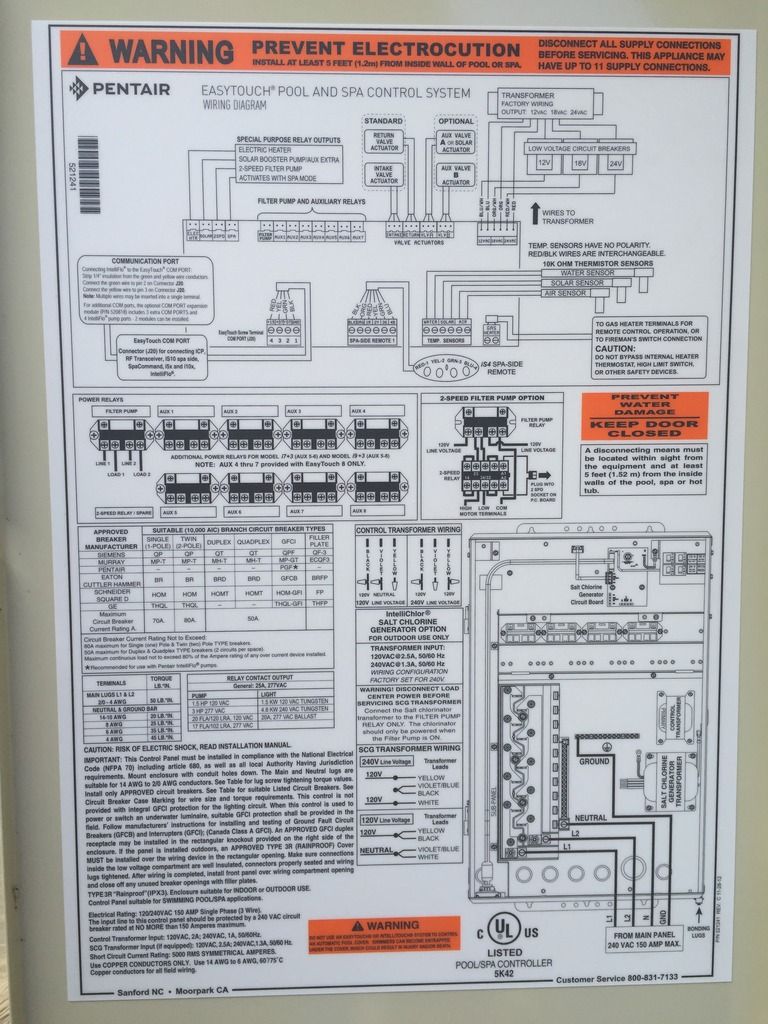
Here are the instructions from the EasyTouch (NOTE: it says connecting a standard gas heater, but not one of their own. Later in the manual it talks about connecting a pentair heat pump?)


Connecting a Standard Gas Heater
For EasyTouch® and IntelliTouch® Control System heater control, there are low voltage dry contacts
that can be connected to most gas heaters or heat pumps with 24 VAC control circuits . The following
connection instructions are for gas heaters and heat pumps with low voltage thermostats.
To connect the heater thermostat cable plug to the EasyTouch or IntelliTouch control system circuit board:
1. Switch the power OFF to the heater.
2. Remove the factory installed jumper from the heater’s “Ext Switch” connector. CAUTION
IMPORTANT: DO NOT disconnect or conductor around the thermostat, pressure switch,
high limit switch, or other safety devices. At the heater, connect the conductors in
accordance with heater manufacturer’s instructions. For older heaters without instructions
for remote operation, connect the conductors to the Fireman’s switch connections in series
with the thermostat, pressure switch, and other safety switches.
3. Run a two-conductor cable from the heater thermostat “Ext Switch” connector to the low
voltage raceway to the Personality board in the Load Center. NOTE: Use 221° F (105° C)
temperature rated conductor for connection to the heater. When connecting conductors
inside the heater, be cautious of HOT internal parts of the heater. Refer to the minimum
temperature rating for conductors recommended by the manufacturer. See the heater
owners manual for details.
4. Strip back the conductors ¼ in.
EasyTouch Control System: Insert the conductors into the GAS HEATER two-screw
terminals (J19) on the motherboard. For heater circuit board screw terminal location, see
below and page 31).
IntelliTouch Control Personality circuit board: Insert the two conductors into the GAS
HEATER (J30) two-screw terminal on the left side of the Personality circuit board. For
heater circuit board screw terminal location, see below and pages 41 and 42).
CAUTION: Be sure that the conductors from the heater to the Load Center or Power
Center are not near or touching any line voltage conductors in the heater. Failure to follow
these instructions may cause the heater to malfunction.
5. Set the Power (Thermostat Select) switch to either “Pool” or “Spa.”
6. Set the “Pool” and “Spa” thermostats to their maximum position.


Here is from the Mastertemp instructions:
REMOTE CONTROL CONNECTIONS
1. Switch off power to heater at main circuit breaker panel.
2. Unbolt and remove the access door panels.
3. Open control box cover (see Figure 21).
4a. To connect a 2-Wire Control (such as Pentair’s IntelliTouch® or EasyTouch® Control
Systems) or a timer:
- Remove the factory installed jumper from the Fireman’s Switch terminals.
- Connect wires between the Fireman’s Switch terminals on the heater and the
relay. Connect wires from the controller or timer to the Fireman’s Switch.
Controller, timer or relay should be sized to handle 24VAC at 0.5 Amp (because
it will be completing the 24VAC control board circuit on the heater as shown in
Figure 22). DO NOT apply line voltage to the Fireman’s Switch terminals. Use
18 gauge wire with a minimum 3/64” (1.2mm) thick insulation rated for a
temperature rise of at least 105°C.
- Knock-outs are provided to route the wires through
the bottom of the control box and past the junction
box.
4b. To connect a 3-Wire Control:
- Connect wires between the control board terminals
on the heater and the external relays, as shown in
Figure 23. Use at least 2 relays per heater, to allow
for an “OFF setting” on each heater mode. Select
relays that can handle logic level switching. DO NOT
apply line voltage to control board terminals.
- Move jumper (as shown on Figure 23) to enable
external control and to disable the heater membrane
pad’s “Pool ON” and “Spa ON” buttons (the “OFF”
key on the membrane pad remains functional).
- Knock-outs are provided to route the wires through
the bottom and the top of the control box and past
the junction box.
5. Close control box cover.


Lastly, it says to run a low voltage line from the Mastertemp to the Easy Touch using 18 gauge wire? And

Yes, i did purchase the screen logic.
 
I hooked my MasterTemp up to my EasyTouch.

Basically, the heater 240V needs to come from the Filter Pump relay, so your heater is never on without your pump.

Then open up the heater circuit board and remove the red jumper wire (that's connected to the "fireman's switch"). Then you need a 2 conductor wire that goes from the heater circuit board fireman's switch to the EasyTouch. It goes into the EasyTouch panel through the low voltage raceway, and up to the back of the EasyTouch circuit board to the HTR connection.

Then the heater has power whenever the pump is on. When the panel calls for heat, it sends a 24v signal from the EasyTouch Panel to the fireman's switch to tell the heater to turn on.
 
Wow, you should write the instructions for Pentair! You boiled it down very succinctly. Question, referring back to my initial picture on the relays, line and load... i do not hook both the Pump and Heater and Intellichlor to the same relay do I? How would they all fit in under the terminal screws? Or do you jumper them to others, if so, what does the wiring look like for that?

Is the 2 conductor wire 18 gauge? That is what I have been reading.
 
When the panel calls for heat, it sends a 24v signal from the EasyTouch Panel to the fireman's switch to tell the heater to turn on.

Not that it is much different, but the ET just provides a dry set of relay contacts.. The heater sends the 24 volts to the ET, thru the relay, and then back to the heater. Basically the ET is nothing more than the "red jumper" you removed from the fireman's switch.

Jim R.

- - - Updated - - -

Wow, you should write the instructions for Pentair! You boiled it down very succinctly. Question, referring back to my initial picture on the relays, line and load... i do not hook both the Pump and Heater and Intellichlor to the same relay do I? How would they all fit in under the terminal screws? Or do you jumper them to others, if so, what does the wiring look like for that?

Is the 2 conductor wire 18 gauge? That is what I have been reading.

You can if you want, run one wire to the relay and then use wire nuts to connect what you want to that one wire.

Jim R.
 
Do you have a picture of this? When you say remove the red jumper wire, where do you put it? Also, on the back side of the mastertemp when you remove the panel, there is an on/off switch. What is that for? It is just above where the gas line is wired in.


I hooked my MasterTemp up to my EasyTouch.

Basically, the heater 240V needs to come from the Filter Pump relay, so your heater is never on without your pump.

Then open up the heater circuit board and remove the red jumper wire (that's connected to the "fireman's switch"). Then you need a 2 conductor wire that goes from the heater circuit board fireman's switch to the EasyTouch. It goes into the EasyTouch panel through the low voltage raceway, and up to the back of the EasyTouch circuit board to the HTR connection.

Then the heater has power whenever the pump is on. When the panel calls for heat, it sends a 24v signal from the EasyTouch Panel to the fireman's switch to tell the heater to turn on.
 
Do you have a picture of this? When you say remove the red jumper wire, where do you put it? Also, on the back side of the mastertemp when you remove the panel, there is an on/off switch. What is that for? It is just above where the gas line is wired in.
You remove that small jumper, and you wire the 18/2 wire to the terminals that previously had the jumper. So now the Fireman's switch, instead of being jumped 4", it's going to the HTR connection on the back of the EasyTouch circuit board.

So like Jim said before, when the fireman's switch is jumped (like shipped from the factory), then you have 24v coming across the jumper wire completing the fireman's switch (and allowing the heater to turn on) - think of it like a light: from the factory with the jumper in place when the breaker is on, the light would be permanently on. You want to be able to turn it on / off through your EasyTouch, so you want to use the EasyTouch as a switch. When you remove the jumper, and connect those terminals that previously had the jumper to the HTR connection on the back of the EasyTouch circuit board, now you've put in a switch. The EasyTouch controls when the switch is flipped on and off, like a light switch. So while the Heater board is sending 24v across one side of the wire coming from the fireman's switch, the EasyTouch may have the connection open (think "light switch off"), meaning that the heater is off. When there's a call for heat, the EasyTouch closes the connection, allowing the 24v to cross the contact closure (switch), making it back to the Heater circuit board, and turning on the heater - a completed circuit just like the jumper does, but only when the EasyTouch wants the heater on.

I'm not sure what the On / Off switch does on the back side - I've never noticed it on mine.
 
Thread Status
Hello , This thread has been inactive for over 60 days. New postings here are unlikely to be seen or responded to by other members. For better visibility, consider Starting A New Thread.