Important electrical question for SWCG hook up.

Jul 1, 2013
68
Cincinnati OH
My 220 Volt pump input has a black red and green wire. My RJ60 SWCG has a black, white and green wire.

My initial assumption was black to black at the same terminal the pump picks up its power after timer control and red pump to white SWCG.

Sounds like red in a 220V hookup is a secondary love wire so not a good thing to hood a neutral white into. Find the neutral wire bundle and wire nit the white SWCG wire into that?

- - - Updated - - -

Additional info...

The white neutral from my pump is wired to ground.
 
Yes I believe that's what you have black and red are hots. Green is ground. It appears your swg is 120 volt so what you are doing is correct black is hot white is neutral. Green is the ground.


Sent from my iPhone using Tapatalk
 
JC,

Looking at the RJ60 manual it says this unit is 220 volts by default. If you want to make it 120 volts you have to move a jumper inside the unit.

So, as shipped it requires 220 volts, meaning the Black and White are your Hot leads where you would attached your 220 volt input power. As always, green is ground.

If me, I would double check and make sure the internal jumper is in the 220 volt position. before connecting it up...

Thanks,

Jim R.
 
Good call to check the manual first JR. Here's the page from the manual.
3ff0168c136407880f48555bc1d41436.png


so based on what JR says just hook the black and whites from the swg to the same terminals that you have the black and red wires from your pump. Then it will turn on and off at the same time as the pump does.


Sent from my iPhone using Tapatalk
 
JC,

Looking at the RJ60 manual it says this unit is 220 volts by default. If you want to make it 120 volts you have to move a jumper inside the unit.

So, as shipped it requires 220 volts, meaning the Black and White are your Hot leads where you would attached your 220 volt input power. As always, green is ground.

If me, I would double check and make sure the internal jumper is in the 220 volt position. before connecting it up...

Thanks,

Jim R.

Yes the RJ60 is meant to be factory configured for 220V and I do have 220V input to the pump, so it sounds like in this case white to red.
 
The white neutral from my pump is wired to ground.
That doesn't make sense. Can you explain that or show a picture?

As noted, the unit looks like it comes wired for 240 by default.

If the unit is set to 240, you wire it to the same supply as the pump so that the unit only gets power when the pump gets power.

Can you show pictures of the wiring and wiring diagram?

What are the black and white wires if the power gets connected at the terminals?
 
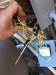
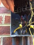
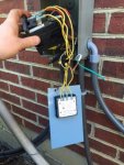
It's difficult to see much in these pictures. The box you are looking at is the electrical box that inputs the power from the 220V power supply, takes the signal from the timer, and outputs power to the pump when the timer is on.

There is a heater that bypasses the timer so lot of wires here.

At the base of the box (right side in the picture). There are two screw terminals. The left terminal (bottom in the picture) had the black hot wire for the pump input and the right terminal (top in the picture) had the red pump wire.

As I mentioned before the white neutral from the pump is wired in with all the ground wires (bare coppers and greens that were grounded through a screw on the metal electrical box).

I have hooked up the SWCG black wire along with the black pump wire and I was about to hook the white SWCG wire to the red pump wire on the other (right or top in picture) terminal on the box then thought to slow down and make sure I have this right.

- - - Updated - - -

IMG_5799.jpg

- - - Updated - - -

Don't know that the second picture is a hole lot better, but you can more clearly see the SWCG bundle of wires. You can see the white and green are yet to be hooked up.
 
IMG_5800.JPG

IMG_5802.jpg

IMG_5803.jpg

- - - Updated - - -

I'm above my quota on pictures.

The last one was of the inside of the RJ60 control panel. The jumper is in the correct position for 220V

- - - Updated - - -

The RJ manual wiring diagram shows two wires hooked up to "load 1" and "load 2". Page 9 of the pdf below. To me this has to mean white wire goes to the red "load 2".

http://discountsaltpool.com/CircuPool-RJ-Series-Chlorine-Generator-Manual.pdf

- - - Updated - - -

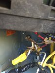
In the pictures above the pump wires have the yellow outer insulation and come in on the extreem left of the bottom of the box. The first picture shows an close up showing the white pump wire grounded with all the copper grounds. The loop that is screwed to the box is not attached in the picture, but you can clearly see the screw behind it.

That is the ground bundle.
 

Enjoying this content?

Support TFP with a donation.

Give Support
Just went back out and checked the pump wiring one more time.

As I showed in the picture above. The white neutral is indeed tied into the bundle of ground wires. What I noticed though is that there is a copper ground wire that was cut too short and not hooked up. It appears that the person that made this mistake decided that the neutral should take place of the ground and there would be no neutral.

Does this mean that whatever unused current will go into the ground rather than back to the electric grid? I stepping beyond my electrical expertise at this point, but this set up certainly doesn't look right.

Thoughts?

And still hoping someone can confirm.....white SWCG load 2 wire to same terminal as red pump wire?
 
Black and black and red and white. That is the correct way.

As far your neutral goes. That's the way it was done in the old days. Before I remodeled my 1955 home, the neutral was tied into the ground inside my meter/main. Go take a look at that panel and see what it looks like. It could be the same.


Sent from my iPhone using Tapatalk
 
Whoever made that mess was not an electrician nor was a permit pulled. Electrician would never kick his own butt by pulling romex in seal tight. Nor is it up to code since romex is not rated for wet locations. Wiring in there is newer than the 1992 house. Color coded romex hit the market around 2000

One last thing is it does not look like the metal encloure is bonded. With all of that wire jamed in there, the enclosure could become hot and next time you touch it you could get shocked. Be careful
 
Black and black and red and white. That is the correct way.

As far your neutral goes. That's the way it was done in the old days. Before I remodeled my 1955 home, the neutral was tied into the ground inside my meter/main. Go take a look at that panel and see what it looks like. It could be the same.


Sent from my iPhone using Tapatalk

This is still true today -- the neutral and ground are bonded together (all connected to the same bus bars) at the main panel -- and nowhere else.

A simple 240V circuit (not a stove or something that has both 120 and 240 components) indeed only uses two hot wires, no neutral.

Just to be pedantically clear, this doesn't mean you're using "the neutral as a ground". It is more correct to say that you're using the "white wire as a ground". Electrically this works, as long as this is a dedicated circuit with this box as the only endpoint. Code wise, however, I don't know if it's legal to have functional "ground" wire colored white instead of bare or green
The concern would be that if someone in the future goes to splice a new 240V component into the circuit, using the white wire as neutral and bare as ground in the new place, a dangerous condition can be created.

I'd at least take a green marker and color *both* ends of this white wire; that's how it's done when a white wire needs to be used as a "hot" in switching circuits or similar. But again, I don't know if that's really code compliant here.
 

Enjoying this content?

Support TFP with a donation.

Give Support
Thread Status
Hello , This thread has been inactive for over 60 days. New postings here are unlikely to be seen or responded to by other members. For better visibility, consider Starting A New Thread.