New 2 speed motor replacement - need wiring help

Apr 26, 2012
12
Yesterday was pool opening day only to find out that the motor was seized up good and tight. The motor I had is an AO Smith 2 speed that is controlled by a 2 speed timer and is wired with 4 wires coming from my timer panel. The only motor I could find locally has a canopy switch on the back but other than that will work fine. I just need some help in getting this motor wired properly to use the 2 speed timer to control the motor instead of the canopy switch . Here are a couple of pics and details.Any help here would be greatly appreciated

Existing wires coming from panel:
White - line
Red - High speed
Purple - Low speed
Green - Gnd

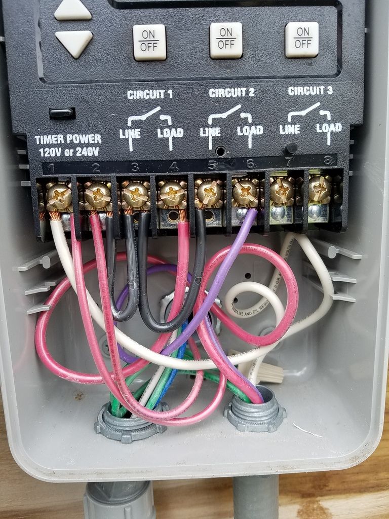
Timer Wiring (wires heading to pump are in conduit on right. Circuit 1=high speed. Circuit 2=low speed):


New Pump Label / Wiring Diagram:


New Pump Connections
 
I know I've seen this question before.

Did a little googling. I think this is what you want to know.

CenturyMotorWiring-11.jpg
 
I actually haven't removed it electrically yet. It's the Carling switch in the bottom left of the last picture in the first post. I'm assuming I can just simply pull off the wires and don't need to do anything else at the motor except connect the leads from my timer?
 
I actually haven't removed it electrically yet. It's the Carling switch in the bottom left of the last picture in the first post. I'm assuming I can just simply pull off the wires and don't need to do anything else at the motor except connect the leads from my timer?
That's what it looks like to me. All you're really doing is moving the switch from the back of the motor to the panel.
 
OK, I wired it as in your pic, unplugged the Carling canopy switch and removed the red and yellow jumper wires. I did not remove the white one as it runs underneath and can't get to it. When I tested it the high circuit runs, but the low circuit does not. Any suggestions?
 
By jumpers, I mean short wire leads. The short black and yellow wires running from the switch to the terminal block were removed after unplugging from the switch.
Hmmmm. Let me study on this a bit.

Okay... looking at the pic I posted, I see another connection coming up from below on the white wire, terminal 1.

If your motor doesn't have that, that's where the white wire to the Carling switch goes. You probably don't have to snake it around behind, just connect it to one of the empty spade terminals on 1
 

Enjoying this content?

Support TFP with a donation.

Give Support
You should have 240 coming in to the timer. The white wire should be 120 volts going from the timer to terminal 1. Note that white is usually used for neutral and not the best choice for a power wire. Put black electrical tape on both ends to identify it as a power wire.

Red goes to terminal 2.

Remove the short black jumper from the switch and the yellow jumper completely from the pump.

The white wire connected to the switch gets removed from the switch and connected to the purple wire. You can connect them directly or connect both to terminal 3.

I don't know the timer wiring, so make sure that that's correct and can only power one set of windings at a time.
 
JamesW, Thanks. That did it. I took the white wire that was connected to the switch and connected it to the 3/4 terminal with the purple low speed wire.

Thank you all for your help.

JP

Sent from my SM-G930V using Tapatalk
 
The end result should be that when you select high speed, 240 goes to terminals 1 and 2 with no power to 3/4 and when you select low speed, 240 volts goes to terminals 1 and 3/4 with no power to terminal 2.

Also, verify that the total HP of this motor is equal to or greater than the old motor.

Total HP is hp x service factor (S.F). This motor has 1.0 x 1.0 for a total of 1.0 total hp.
 
The pump is a Hayward Superpump that had a 1 hp motor and a SF of 1.0. I quickly replaced that one to put in a 2 speed pump that was also a 1 hp but had a 1.5 SF. The new 2 speed replacement pump is a 1 hp and a SF f 1.0 so back to where I originally started. I'll grab my DVM and do some voltage checks as you suggested.
 

Enjoying this content?

Support TFP with a donation.

Give Support
Thread Status
Hello , This thread has been inactive for over 60 days. New postings here are unlikely to be seen or responded to by other members. For better visibility, consider Starting A New Thread.