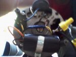
I was recently doing some pressure washing and the area housing my pump, junction, and timer got wet.
The motor for the timer does not work at all. The gfci was also ruined. I was able to bypass the timer and outlet with direct lines from the junction to a switch from switch to the motor. The pump ran fine for nearly a week on 120V flawlessly.
I turned off my breaker and disconnected everything to clean up the wiring and now the pump will not fire. I deleted the switch in an attempt to prove the pump was not fried and it did start.
I am at square one now with no connections to the motor or from the box.
The Pump and Motor Information are as follows according to the diagram on the motor:
Pump Model is 72743nc. The closest thing I can find to a manufacturer is SPLAPOOL.
I cannot find any information to this setup anywhere and as far as I know there is no manual.


The motor for the timer does not work at all. The gfci was also ruined. I was able to bypass the timer and outlet with direct lines from the junction to a switch from switch to the motor. The pump ran fine for nearly a week on 120V flawlessly.
I turned off my breaker and disconnected everything to clean up the wiring and now the pump will not fire. I deleted the switch in an attempt to prove the pump was not fried and it did start.
I am at square one now with no connections to the motor or from the box.
The Pump and Motor Information are as follows according to the diagram on the motor:
- Motor Model: CS4M249I22L
- Volts:115/230
- Hz:60
- HP:1.0
- ENCL: DP
- Max Load Amps 11.5/5.7
- RPM:3450
Pump Model is 72743nc. The closest thing I can find to a manufacturer is SPLAPOOL.
I cannot find any information to this setup anywhere and as far as I know there is no manual.


