And, so begins the build of my automation system. Intended features:
This will be based off a Raspberry PI (happens to be an older Rev 2 version). It has plenty of GPIO handle this. Best of all, it can easily be a web-server, run a database back-end, and can be programmed through just about whatever programming language you want. This will be a mix of PHP for the web-interface, python for the guts of the logical control. Sample history, temperature data, and run states will be stored in mysql database.
I know I'm not the first to do this. But, I haven't seen a DIY job that ties all this together in an moderately easy to use open source package (am I missing it?). I will share full code and want to streamline the setup for any others that want to duplicate this.
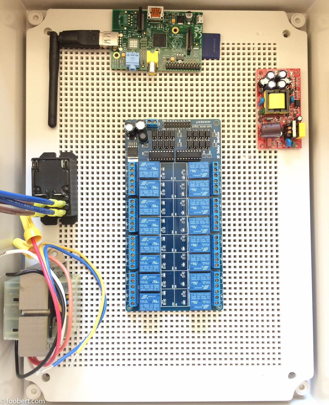
Let's get started. A quick floor plan layout of the hardware in the enclosure.
The major parts list:
Excluding the valve actuators, the hardware for this is quite simple and cheep.
I'm choosing not to automate the sensing (ala, ORP + PH). It's certainly technically feasible, but, seems more trouble than it's worth from a cost/benefit/maintenance standpoint.
This will be a phased approach. First part is basic pump control, chlorination, valves, and heater. Second phase will be the web-UI. Pressure monitoring will happen later. Solar control once I have solar panels installed to bother with. Acid injection when I get tired of pouring acid in
- Valve control for intake, returns, sweep, and solar.
- Pump control of the 4 programmable speed presets.
- Solar temperature controller
- Heater control and temperature modulation.
- Mobile friendly web-enabled control w/manual overrides (ala, kick on spa for 45 minutes at 100˚).
- Salt-water generator run-time control through FC sample data input.
- PH control via acid pump controlled through PH sample data input.
- Water chemistry history record and at-a-glance problem identification.
- Filter pressure monitoring to identify back-flushing time.
- Lighting control
This will be based off a Raspberry PI (happens to be an older Rev 2 version). It has plenty of GPIO handle this. Best of all, it can easily be a web-server, run a database back-end, and can be programmed through just about whatever programming language you want. This will be a mix of PHP for the web-interface, python for the guts of the logical control. Sample history, temperature data, and run states will be stored in mysql database.
I know I'm not the first to do this. But, I haven't seen a DIY job that ties all this together in an moderately easy to use open source package (am I missing it?). I will share full code and want to streamline the setup for any others that want to duplicate this.
Let's get started. A quick floor plan layout of the hardware in the enclosure.
The major parts list:
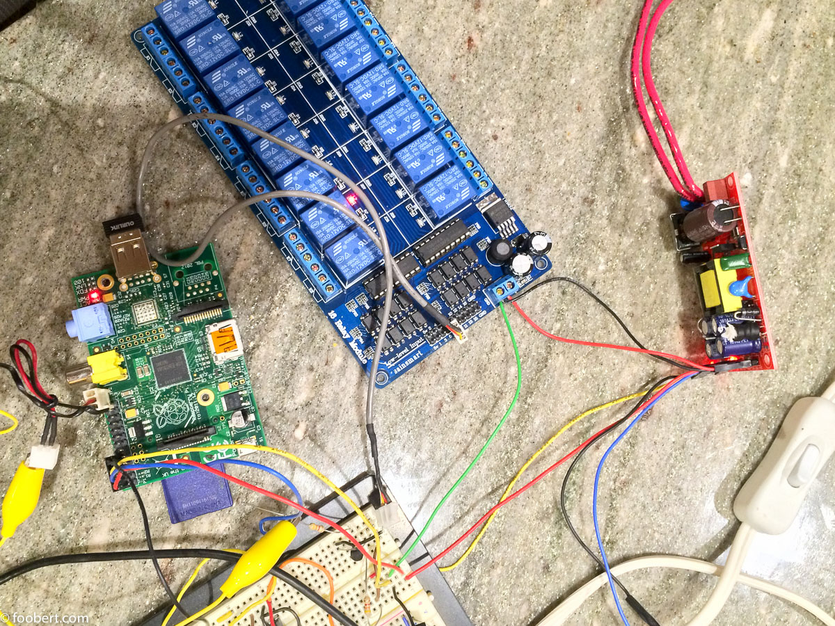
- Raspberry Pi w/ wifi adapter -- $40
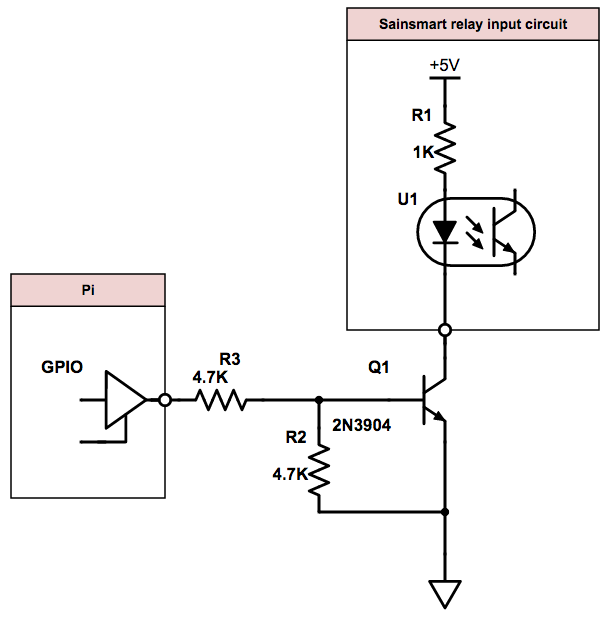
- Sainsmart 16-channel relay module -- $15
- Valve actuators. I went with Intermatic -- $85/ea
- 24-volt Transformer -- $15. 40VA is a little wimpy, but, I don't plan to move more than 2 valves at once.
- AC-DC power supply -- supports 1 amp each of 12V and 5V. -- $12
- DS18B20 digital temperature sensors -- cheep
- Outdoor rated enclosure. -- $40. Since I'm networking the Pi via wifi, plastic was my friend.
Excluding the valve actuators, the hardware for this is quite simple and cheep.
I'm choosing not to automate the sensing (ala, ORP + PH). It's certainly technically feasible, but, seems more trouble than it's worth from a cost/benefit/maintenance standpoint.
This will be a phased approach. First part is basic pump control, chlorination, valves, and heater. Second phase will be the web-UI. Pressure monitoring will happen later. Solar control once I have solar panels installed to bother with. Acid injection when I get tired of pouring acid in