A lot of solar controller plumbing diagrams I have seen only use 1 automated 3 way valve that opens when the solar controller senses heat up in the panels and then shuts it off when the panels either cool down or optimal temp is reached for the pool...The problem I see is this....
When the controller shuts off the valve, the water drains down on the return side through the check valve, but how does the water drain from the supply side with the 3 way valve completely closing off that line??
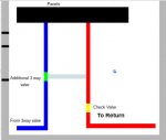
I thought about using a second automated 3 way valve like in the picture below to allow the water to connect from the supply side to the return side through a bypass line so that the water can drain on the supply side as well... Am I missing something as to why this is not done normally on a solar panel installation?
Thanks...
When the controller shuts off the valve, the water drains down on the return side through the check valve, but how does the water drain from the supply side with the 3 way valve completely closing off that line??
I thought about using a second automated 3 way valve like in the picture below to allow the water to connect from the supply side to the return side through a bypass line so that the water can drain on the supply side as well... Am I missing something as to why this is not done normally on a solar panel installation?
Thanks...