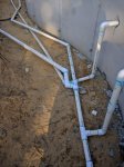
a) 2" pipes, b) head loss around bends

wet_labrador

0
Bronze Supporter
May 12, 2016
37
new jersey
a) 2" pipes, b) head loss around bends

our pb indicated that he uses 2" pipes. now that the pipes are actually installed, i noticed that the output from the pump is a single 2" pipe that connects to a "T" of two 1.5" pipes. those 1.5" pipes feed 3 returns, 1 return from the left side of the "T" and two returns from the right side of the "T". The first of those two returns on the right side is 1 foot from the "T" whereas the other is roughly 20' from the "T" which is roughly equidistant to the other return on the left side of the T. will the downstepping in pipe diameter help or hurt head loss? are "T"s usually used and if so how do they impact headloss versus other ways of accomplishing the same goal?

secondly, our pb when he showed his demo pump pad, showed 2" pipes with sweep elbows. yet nearly every pipe in the ground is either a 45* angle or a hard 90* angle elbow with no sweeping to it. /\ or |_. do people usually use sweeping elbows in ground? it seems odd that they go through all that trouble to plump the equipment with sweep elbows but then move most of the water to the pool with hard angle elbows? am i wrong here?

what should i expect? meaning what's ideal?

it's a mountain lake shaped pool. 25k gallons.

- - - Updated - - -

given this configuration:
Analysis of Plumbing Loops and Other Configurations

it looks like semi binary loop with return #2 omitted.

- - - Updated - - -

the difference being that everything after the initial T, leading up to the returns, is 1.5". that link seems to indicate the dowstepping happens only for 2' on the 1.5" return. the pvc off of which all returns stem is 1.5, which is fed by a T of 2".

|_______|_______| <----all 1.5"
P_____| <----all 2"

P is pump

- - - Updated - - -

as an aside, assuming they skimped on the underground elbows, and possibly even semi binary pipe sizing, i guess attempting to run a semi binary configuration is a plus, right? they were willing to pay for extra pipe in an attempt to get equal return pressure?
 
Re: a) 2&amp;amp;quot; pipes, b) head loss around bends

our pb indicated that he uses 2" pipes. now that the pipes are actually installed, i noticed that the output from the pump is a single 2" pipe that connects to a "T" of two 1.5" pipes. those 1.5" pipes feed 3 returns, 1 return from the left side of the "T" and two returns from the right side of the "T". The first of those two returns on the right side is 1 foot from the "T" whereas the other is roughly 20' from the "T" which is roughly equidistant to the other return on the left side of the T. will the downstepping in pipe diameter help or hurt head loss? are "T"s usually used and if so how do they impact headloss versus other ways of accomplishing the same goal?
2 - 1.5" pipes have less head loss (flow split) than 1 - 2" pipe so that is actually better setup than a single 2" pipe.


secondly, our pb when he showed his demo pump pad, showed 2" pipes with sweep elbows. yet nearly every pipe in the ground is either a 45* angle or a hard 90* angle elbow with no sweeping to it. /\ or |_. do people usually use sweeping elbows in ground? it seems odd that they go through all that trouble to plump the equipment with sweep elbows but then move most of the water to the pool with hard angle elbows? am i wrong here?
If the swept elbows are DWV elbows, which they usually are, I would not use them. They have smaller glue area and can fail much easier under pressure. Also, depending on the number of elbows, it may not make that much of a difference.

Forgot to add that the configurations don't really matter much. If you notice the flow rates, they are not much difference you would never be able to detect a difference.
 
Re: a) 2&amp;amp;quot; pipes, b) head loss around bends

thanks for the quick reply. good point on negligible differences in flow rates between loop configs. i noticed that reading further. also good to know that the sweep elbows underground are more resilient. thanks for that.

i guess the head loss is my biggest worry. trying to minimize it as much as i can such that i can run the pump at a low of speed as possible yet still get high flow through the heat pump to keep temps up (without paying a kidney to the electric co).

my pb doesn't seem to keen on installing pressure gauges into the pump input and outputs to figure out head loss in a such a way that i can optimize the variable speed pump, so i'm trying to note all the pipes, their diameters, their lengths and their configs so i can maybe do it all once he leaves, if need be.

my pb is a pretty reasonable person, so i think i can convince them to work with me on these things.
 
also good to know that the sweep elbows underground are more resilient.
I think, you misread what I wrote. Just the opposite. Swept elbows are usually DWV elbows which I would NEVER use on a pool. They have smaller glue areas that can easily fail.
 
Knowing what the pump is doing gives me piece of mind, but is not really a necessity. Your pump curve and filter pressure can tell you most of what you need. But that said, I love the convenience and instant number from my FlowViz flow meter with the VS pump. I bought one, located it in a nice visible place, and used it in place of a Jandy check valve. I swapped it into my other Jandy check valve to also know the flow on my solar heating circuit. They have higher friction loss than a Jandy check valve, but you could eliminate the loss by only mounting the flow meter for fine-tuning, knowing that your flow will be ever so slightly higher without the FlowViz. You can buy just the after-market FlowViz meter to put in an existing Jandy check valve (right side picture in the link). TFTestkits.net

I found PVC sweep elbows ($10 each!), but I honestly can't imagine they're any better. The design of mine are narrower through the throat of the sweep than a regular elbow. They look kinda cool, but I'm not convinced about lower head loss.
 
yeah i was hoping to avoid paying 150$ for the flow meter.

i was thinking i'd remove those two bolts on the pump and attach those gauges to them to temporarily measure the head loss. maybe that's not worth the trouble.

the pb was saying i don't need a check valve between the salt water generator and the heat pump behind it, but the manual for it seems to suggest that there should be one and i recall reading here that super chlorinated water flowing back into the heat pump could prove problematic if the run between the two was less than a foot. (otherwise it disperses quickly to nominal amounts).

i guess i'm a little bummed now that i know the difference in jet flow between the various plumbing loops is negligible, yet the differences in head loss seem to be noteworthy. seems to me that 3' of head loss versus 11' is considerable?

lastly, with all of the elbows in those pipes, how to i go about figuring out how much loss of head they induce? is that the normal amount of elbows one must use? or was there a small lack of regard for head loss due to the desire not to run longer straighter pipe or dig out wider?
 
I'm confused why your bummed.... Sounds like a few here have told you this was a non issue in diff words. On a rectangle pool , pvc looks neet and clean. Your pool doesn't have a straight wall. I commend your builder for not using flex. He could of done it in 1/4 of the time. Things could always be neater.I know you can't see my face right now but I'm smiling while I saying..... Get a real problem.:D
Don't take the wrong way ... Just having fun while putting in my 2 cents.
Kris
 
Why are you so concerned with head loss? In most cases, the type of fitting is irrelevant. What matters much more is pipe size, the type of filter and backwash valve and the number of parallel runs to and from the equipment. Everything else is in the noise.

Head loss is not easy to calculate but if you can give me a very detailed drawing of lengths and fittings, I have models to do so. I also need the make and model of pump because that also determines head loss because it is the intersection of the plumbing head curve with the pump head curve which determines the operating point and resultant head loss and flow rate.
 
kris, you're right, i appreciate the candor.

mark, hoping to run the pump at the lowest speeds... worried i can't flip the electrical bill. the heatpump is optimal at 60gpm, and my pumps small from what i understand, so i don't think i could run the heatpump with the pump on anything but the highest setting, which is pricey. i'll go measure everything and get back to you.

sorry, guess i got rookie jitters?
 

Enjoying this content?

Support TFP with a donation.

Give Support
Some people over-estimate the friction loss from fittings because of the way the numbers are provided. For example, say friction loss in a table for 2" fittings includes 3.8 for a 90 degree elbow. The number means 3.8 feet of equivalent pipe. So the calculation for friction loss (from tables) is 3.8 divided by 100 times the friction loss for your flow rate in 100 feet of pipe. Assuming 60 gpm and 2" pipe, that might be 2.5 PSI per 100 feet. So the loss in the elbow is 0.095 PSI, call it 1/10th of a PSI. Put 20 of them in your circuit and you get 2 PSI of head required to push water through all 20 of the 90s. If you also have 200 feet of pipe, that needs 200 divided by 100 times 2.5 PSI = 5 PSI of head to push the water through the straight runs. 45s are a tad under half what a 90 is, but using 2 feet of equivalent pipe, and 10 of those, you get 0.5 PSI friction loss. So, 5 PSI from pipe and 2.5 PSI from fittings.
(numbers from engineering toolbox, which are higher than other tables)

I think OP is like me. When I started out I was dead set on getting super-low operating costs, e.g. VS pump, sweep 90s, 45s where possible, etc. I've done irrigation plumbing where the numbers are bigger, so that's my instinct. From your pictures, my impression is that your builder put good effort into using 45s where possible/sensible and straight runs of pipe. Also, splitting the returns cuts friction loss a lot.

Finally, with a VS or 2-speed pump. On low speed, the friction loss is bordering on negligible. My little system uses 220 watts to pump 25-30 GPM on low, against 4 to 6 PSI of head. At that flow, fitting head loss is extremely low, and I'd guess the filter is around half or more of the head loss. The 2 PSI rise from clean to dirty is the work being done solely by the filter. No help if you need 60 GPM in the heater, but good when the heater's not on.

I hope this is helpful.
 
Thread Status
Hello , This thread has been inactive for over 60 days. New postings here are unlikely to be seen or responded to by other members. For better visibility, consider Starting A New Thread.