wiring help replacing transformer Pentair Minimax NT heater

Jun 24, 2007
75
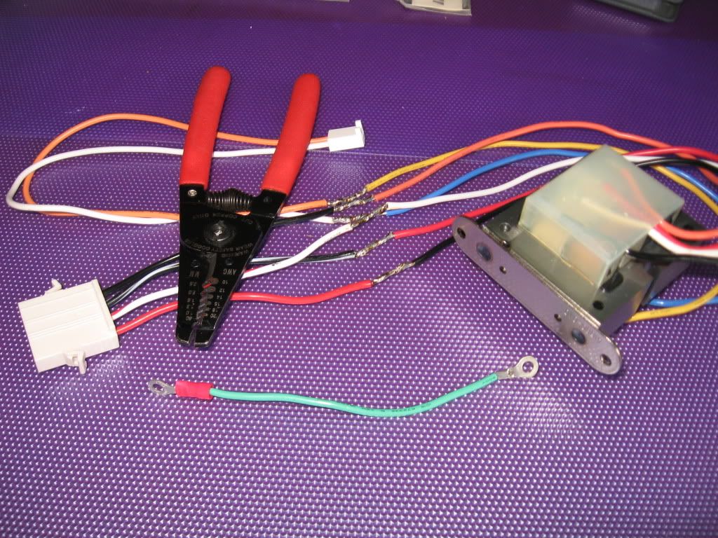
I believe a lightning surge blew transformer on my Pentair Minimax heater. PB did not tighten ground wire in easytouch panel. I could pull the wire out of the grounding block so easy with my little finger. I suspect that caused the "frying" of the transformer. I used an ohm meter and get no voltage out of the orange white wires so I am sure it is gone. The Pentair transformer 471571 is $50-$70 to replace. Made in China and imported by Bestwill. The advantage is that the two plugs are wired in place so it is a simply plug n play replacement. I wanted to save some money so I searched for the exact spec transformer and found a White/Rogers replacement that has the same written specs and has the same weight and measurements and is less than $20 at http://www.grainger.com but one disadvantage. The wiring has different colors and am afraid of just wiring it the same and trying it so I wanted to ask for help here.

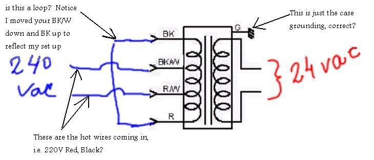
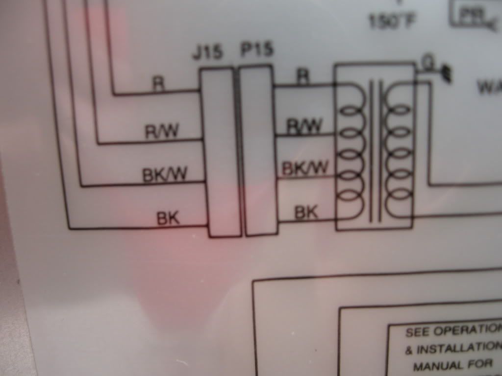
I looked at the Pentair install manual wiring diagram but it doesnt give much help. It shows the wire colors coming out of the transformer but doesn't tell you what the specific color connects to (i.e. power, ground, 240, 120). Actually one wire is even out of order on their diagram. The input plug and wires coming off the transformer itself actually has the wires in this order (top down) Black, Black-White, White-Red, Red and the diagram (top down) shows Black-White, Black, White-Red, Red. I'm not sure if that means anything or matters at all.

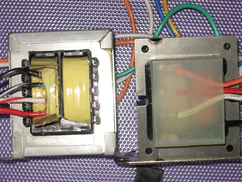
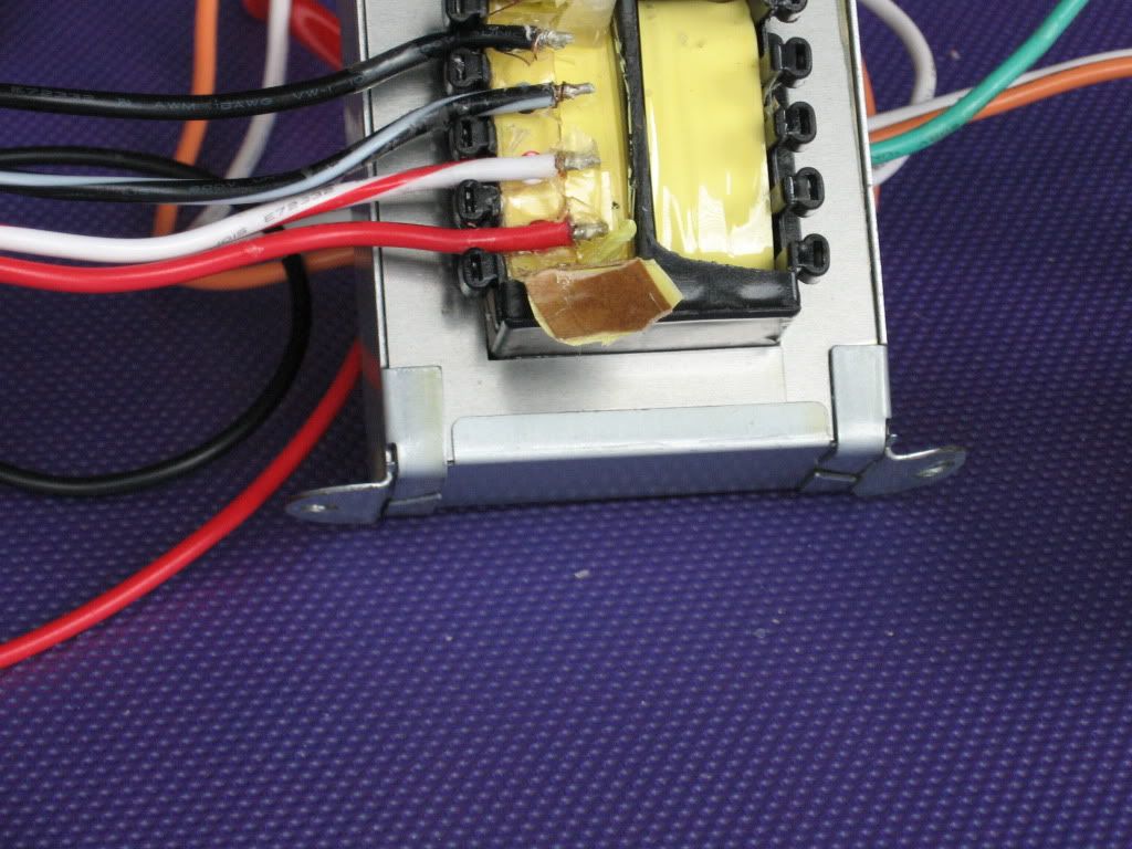
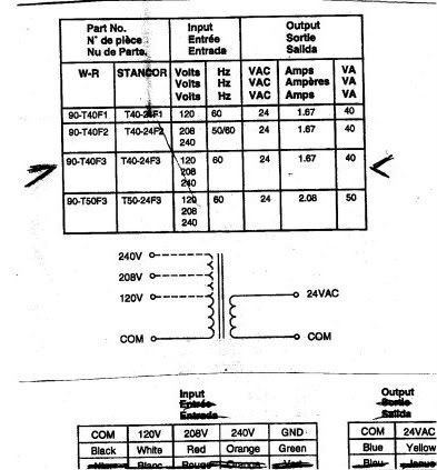
The new White/Rogers transformer colors (top down) are Orange, Red, White, Black. Even though they come off in a different direction (soldered on the transformer)from the original should they be connected the same order? So, new/old : Orange = Black; Red = Black-White; White = White-Red; Black = Red. ??

On the other side of the transformer are the two 24V out put. Old transformer was (Ground) then White wire, Orange wire. New model (has no extra ground wire so I assume the chasis is the ground) then Blue wire, Yellow wire. So, new/old: Blue=White; Yellow=Orange. ??

The job is just to solder the old plugs in place in the correct order. I do know that the White/Rogers came with a sheet that tells me their colors on the Input mean: COM=Black; 120V=White; 208V=Red; 240V=Orange; GND=Green (there is no green). For the out put COM=Blue; 24VAC=Yellow

Where am I right? Where am I wrong? Input is greatly appreciated and I hope this can be helpful to all of our Pentair heater owners who want to save $$ on replacing transformers. I might be able to post pictures if I can figure it out again.

Thanks,

Edited for font size. JasonLion
 
Pics of the two are below.

IMG_0245.jpg


The old Pentair transformer had a black plastic cover that I just broke off to see inside. Notice how the wires go opposite directions from the new one but when opened it up, it looks like they solder at the same point inside. It looks like all four wires soldered to the same band (the creme looking tape covering wires in the first picture). That I do not understand.

IMG_0247.jpg
 
JasonLion said:
The wires are connected to very fine wires that you can't see, which go into the interior of the transformer. The yellow stuff is then added to provide physical support and insulation.

so would you guess that the bottom wire (red on the old one) is in fact COM (which I suppose means ground)? according to the new instructions the bottom wire - black is COM.
 
Trying to compare transformers by their external wire count and color is futile. Transformers may be wired in any conceivable configuration, with multiple coils which could be isolated or connected in any ratios. Outward physical characteristics are pretty rarely indicative of the internals of the transformer. We would need to know the actual electrical specs on the new transformer to give you any guess as to how it should be wired, if at all.
I think, though, that I can tell you a little about the one that went bad, ASSUMING that the Pentair info I have matches YOUR model...

Your original transformer is designed for dual voltage connection, with the coil primary specifically tapped for 1/4 - 1/2 - 1/4 ratio.
Schematically, it looks like this:
xform.gif


Here's how it would be wired for 120 volt operation:
120vac-xform.gif


and this would be the 240 volt wring:
240vac-xform.gif


Basically, all you need to do is generate 24VAC to the P4 connector (white and orange wires - polarity is not important). You need some transformer capable of delivering that from either 120 or 240 volts whichever you are using, and wire it accordingly.
I strongly suggest that if you don't have comfortable electronics ability for that, that you either find a guaranteed replacement part or some qualified electrical help.

[edit]Oh yeah - the ground wire... The ground connection is only to the transformer case, NOT to any of the coil wires. I seriously doubt that the quality of your original ground wire had anything to do with the transformer burning out. It only serves as a safety in the event of a wire-to-case short within the transformer[/edit]
 
Ohm_Boy said:
ASSUMING that the Pentair info I have matches YOUR model...

Your original transformer is designed for dual voltage connection, with the coil primary specifically tapped for 1/4 - 1/2 - 1/4 ratio.
Schematically, it looks like this:
xform.gif


and this would be the 240 volt wring:
240vac-xform.gif


Basically, all you need to do is generate 24VAC to the P4 connector (white and orange wires - polarity is not important). You need some transformer capable of delivering that from either 120 or 240 volts whichever you are using, and wire it accordingly.
I strongly suggest that if you don't have comfortable electronics ability for that, that you either find a guaranteed replacement part or some qualified electrical help.
Ohm Boy, Thanks for the input. And thanks for taking to the time to draw something up and try to help me. Sounds like you are the right guy to speak to this issue.
Interesting thing I noticed today when I remove the side cover to the heater. There was an updated wiring schematic on the back of the door. It does not exactly match the owners manual (but does match the plug on the old transformer) so Pentair made a change but did not update the manual that came with my heater. However the diagram on the door is correct. So looking at your 240v diagram (which comes from the manual) is inncorrect for my transformer.

The order of the wires on my old transformer and diagram on the door is

(top down)
Black---------------
Black-White---------
White-Red-----------
Red-----------------

That is all just to say that I now see a diagram that matches my heater/transformer originally installed and that is good. I was hoping to be able to trace where the wires went on a schematic and determine what to hook it up to on the new transformer but according to your post it really don't matter.

The specs for the new White/Rodgers transformer is: input 120v/208v/240v and 60Hz COM - BLK. 240v and COM is the top and bottom wire. Yellow and Blue will go to the P4 and produce 24VAC
wiring001.jpg

I am running 240V so wouldn't I wire it as I described above just straight accross Orange = Black; Red = Black-White; White = White-Red; Black = Red. :?:

I am fine with working on this but wanted the expertise of someone who knows transfomers to understand . If I turn it on and don't get 24V from the blue and yellow wires I will know something isn't right. I would check the blue and yellow with a volt meter before plugging that into the panel so as not to fry the panel if the VAC is too high. Actually when I trace the wires around in the heater it looks like the power coming in from my panel (240v) eventually (after the switch etc.) goes to the top and bottom wires. Thoughts?
 
Yes, if you are wired for 240, then (according to my diagram) you should have 240 volts from the connector on the red and the black wires. The R/W and B/W should just be jumpered together at the female side of the connector, so they may be ignored now.
First, check your new transformer using an ohmmeter to see if there is continuity from any terminal to the transformer case. There should not be. If there is, you will have difficulty with a 240V setup.
You can verify 240 between R and B with a voltmeter, and if good, use these wires to connect to the COM and 240 terminals of your new transformer. It should not matter which wire goes to which terminal, and there is no polarity for AC voltage. Tape the R/W and B/W off, as they won't be needed.
That should give you 24Vac on the secondary wires. You may see ~27v or so with no load. Once confirmed, you should be good to connect to P4 W&O wires. Again, it will not matter which wire goes to which terminal.
 
I have fried my new transformer and I need your help. I think I went wrong somewhere.
Ohm_Boy said:
Yes, if you are wired for 240, then (according to my diagram) you should have 240 volts from the connector on the red and the black wires.
I assumed you meant my Black and Red wires since my diagram was slightly different.
(top down)
Black---------------
Black-White---------
White-Red-----------
Red-----------------

I checked my voltage and I am reading 240V coming in at the Term Block AND on the top and bottom wires to female plug (Black and Red). BUT now I am really confused. I should have followed your diagram or clarified with you first but it made sense the way I did it. So, let's assume for discussion we are doing this according to your diagram since you said “my diagram”. (Probably what you meant for me to do) You are then really suggesting 240V on the 2nd wire down and the 4th (bottom) wire?

240vac-1.jpg


Ohm_Boy said:
The R/W and B/W should just be jumpered together at the female side of the connector, so they may be ignored now.
Did you mean the top wire and 3rd wire down?

The reason I am asking all the questions is that this really doesn't seem to follow your diagram. IF I understand your diagram (in blue to show 240V comes in on the 2nd and 3rd wires... R/W and Bk in your diagram. I checked the center two wires for voltage on the female plug and got nothing but the B/W and Red had 240V. (again according to your diagram not reality.)

If using the center two (from the original transformer) is what you meant, I really screwed this up. Since I had posted that my wires were actually different order than your diagram.....
(top down)
Black---------------
Black-White---------
White-Red-----------
Red-----------------
I assumed you meant Black (my top wire) and Red (my 4th or bottom wire) were correct for 240V when you said: “you should have 240 volts from the connector on the red and the black wires.”


Ohm_Boy said:
You can verify 240 between R and B with a voltmeter, and if good, use these wires to connect to the COM and 240 terminals of your new transformer. It should not matter which wire goes to which terminal, and there is no polarity for AC voltage.
I did just that before plugging in the transformer. Again, I checked the Black and Red on the plug and got 240V. I got no other readings with any combination of the 4 wires so assumed this had to be right, Black and Red carry the 240V. My new transformer directions clearly show the top wire is 240V and the bottom (4th) wire is COM.


Ohm_Boy said:
First, check your new transformer using an ohmmeter to see if there is continuity from any terminal to the transformer case. There should not be. If there is, you will have difficulty with a 240V setup.
I did this too and no continuity from any wire to the case.

Ohm_Boy said:
Tape the R/W and B/W off, as they won't be needed.
Here I just wired it to the same two wires (2nd and 3rd down, B/W, W/R) as it was from the factory in case it ever goes to 120V. The Pentair chassis has a blue plug with the necessary loops for 120V and a Red/Brown plug for 240V which takes care of how the loops work for different volt selected. Mine is plugged into the "Red" square plug as it was factory set. Here is a look at it before taping it all up.

002.jpg

I am lost as to why the transformer fried. As soon as I flipped the breaker switch I heard a sound like plastic crinkling up and smoke and poof, it is gone. I still really would like to use another new Rogers/White transformer if I can figure out how so that anyone in the future can save $50 IF it can be done. The cost is roughly $20 as compared to $50-$70. What do you think? Alot of questions in here but hopefully I have revealed something that gives you a clue as to what went wrong.

This can all be terribly confusing (as it has taken a LONG time to get this all written for this post :hammer: 
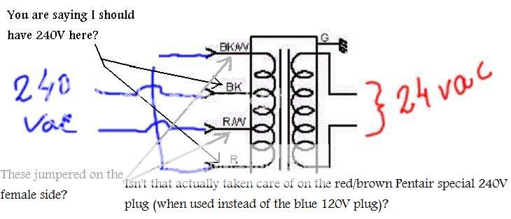
) so let's use the real diagram from MY diagram going forward so I don't confuse you any longer.

Maybe it can all be explained by the questions in this diagram? However I don't understand how power comes in on the center two wires per your drawing and yet the female plug reads no voltage on the center two wires.
240vac-xform1-1.jpg
 
I was afraid of that.
The diagram I posted was of the original transformer in the original configuration. It showed what the connections would be for each voltage setup.
Your replacement transformer is not like the original. To connect it to 240, you would use the COM and 240 terminals, and wire 240V to those two terminals. You ignore the other terminals. Since you will no longer be using a dual-voltage setup because of the new (different) transformer, you will also only need to use the two wires (which SHOULD be R & B) from the plug which have 240 volts on them, and ignore the other two (SHOULD be r/w & b/w) which are just connected to each other at the plug. Then you take the two 24V connections and hook them to P4.
Something like this:
xform2.gif

There is no significance to the position in which I draw the wires on the connector, and I am showing, albeit crudely, a meter checking to confirm 240v on the two wires to the transformer. Whichever two carry the voltage, those are the two you will use. The two without voltage will not be connected with your new replacement transformer.
 
Ohm_Boy said:
I was afraid of that.
The diagram I posted was of the original transformer in the original configuration. It showed what the connections would be for each voltage setup.
Your replacement transformer is not like the original. To connect it to 240, you would use the COM and 240 terminals, and wire 240V to those two terminals. You ignore the other terminals. Since you will no longer be using a dual-voltage setup because of the new (different) transformer, you will also only need to use the two wires (which SHOULD be R & B) from the plug which have 240 volts on them, and ignore the other two (SHOULD be r/w & b/w) which are just connected to each other at the plug. Then you take the two 24V connections and hook them to P4.

I am showing, albeit crudely, a meter checking to confirm 240v on the two wires to the transformer. Whichever two carry the voltage, those are the two you will use. The two without voltage will not be connected with your new replacement transformer.
Thanks for the fast response. My transformer list 3 input voltages 240V (which is the top wire, orange) 208V (2nd wire, Red), 120V (3rd wire -White) and COM bottom wire-BK. I understand you to be saying to connect the new transformers top/orange wire to my plugs top wire (BK) and the Com-BK new transformer wire to the plug bottom wire - Red. I further think you are saying that it doesn't matter if I go Orange to Red and BK to BK. You are also saying NOT to even connect other two wires (Red-208 and White 120).

Your description is the way I connected it the first time (it fried) after verifying that I had 240V on the plug's BK & Red terminal. I tested it exactly as your diagram indicates. However, I did hook up the two center wires but assumed they did nothing until in a 120V configuration (based on the blue plug inside). So, what made it fry? What will be different this time? Does it have something to do with the two center wires?

Just for the record hre is a photo I took today of my actual label to clarify even though I reversed the order of 1-4, Red shows on top and Black bottom, still they are in the same order on the plug:
004.jpg
 

Enjoying this content?

Support TFP with a donation.

Give Support
I understand you to be saying to connect the new transformers top/orange wire to my plugs top wire (BK) and the Com-BK new transformer wire to the plug bottom wire - Red. I further think you are saying that it doesn't matter if I go Orange to Red and BK to BK. You are also saying NOT to even connect other two wires (Red-208 and White 120).

I believe that you have it. Your new transformer is designed to be connected to EITHER 120 208, or 240 volts. Your available voltage determines which tap you connect. Since you have 240, you'll use the 240 connection. The other two will not apply.

=============== 240 volt wiring ================

On the transformer side you'll use the COM/Black for one connection, and the 240V/Orange one for the other, and do not connect the 120 nor the 208 terminals to anything. Repeat: do not connect the 120 and 208 wires to anything.

Back on the plug side, two wires should carry 240 volts. Black&Red, or Black/White&Red/White, or top and bottom, middle two, ... whichever. The important thing is to locate the two wires supplying 240 volts between them, and ignore the other two. Repeat: do not connect the two non-live (allegedly rd/wt and bk/wt) wires to anything.

Now, the two wires carrying 240 volts connect to the COM and 240 wires of the transformer. It does not matter which-to-which, as long as one 240v wire connects to COM, and the other 240v wire connects to 240.


================ 24 volt wiring ================
On the other side of the transformer, the two 24v wires will connect to the two P4 wires. Again, it does not matter which-to-which as long as one 24v transformer wire connects to one P4 wire, and the other 24v transformer wire connects to the other P4 wire.

Insulate all the connections with wire nuts or electrical tape. Also tape the bare ends of any loose, non-used wires so that they won't make any electrical contact with anything else. Repeat: NO electrical connection to the four unused wires (two from the plug, two from the transformer) They don't connect to each other, or to anything else.

Done. Enjoy!
 
Just an update for anyone interested in trying to replace your Pentair transformer with the one I mentioned above. I rewired with just the orange and black wires for 240V and it works fine. Voltage was exactly the same as the Pentair transformer. Both were at 26.7V. I have also blown my DDTC board but this transformer works when you know how to wire it. I hope someone else benefits from my trial and error and saves some money. Regards,
 
You are very lucky that the lightning strike did not also blow your Easy Touch, Intelliflo or any other electronics connected in your home. You should really consider getting a surge protector for your home. I installed one one my main panel, and also one on my Easy Touch panel. The intelliflo is especially susceptible to voltage surges.
 
Thread Status
Hello , This thread has been inactive for over 60 days. New postings here are unlikely to be seen or responded to by other members. For better visibility, consider Starting A New Thread.