Pool Pump Timer Connection Problem

Sep 24, 2015
15
FL
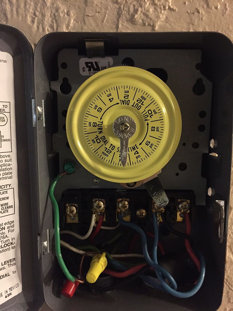
Being the genius that I am I didn't think about taking a picture of the cable connections on the broken pump timer of my GF's pool before exchanging it for a new one. I believe either the red cable going to the first pole is incorrectly connected or the white one. The pump does turn on right now but it looks like it's only running at half speed. In my totally amateurish way of diagnosing the problem I would say the pump is running at 110V instead 220V as its supposed to but I really have no idea what I am talking about.

The timer is a T104M DPST (220V)

Here are the instructions.

http://www.intermatic.com/~/media/i...es/24_hour/t100_series/t104m_instructions.pdf

If you know how to fix the problem, please explain it as if you were talking to an idiot. I can measure volts and continuity. That's the extent of my knowledge of electricity.

 
If you are still having trouble. I can offer this. As long as the timer is only feeding the pump, there should only be one wire that you attache to each connection point. It look like there are some connections with multiple, user connected, wires on them. Now if you also feeding power to another device like a SWG then you would have multiple wires.

As danpik said - 1 and 3 are your incoming from the 220 supply and 2 and 4 are the outgoing to the pump and whatever else you might have connected.
 
terminals 1 & 3 are the supply voltage. one of each of the oncoming lines to these. 2 & 4 go to the pump

Ok so I should be measuring 220V on the cables that go to 1&3? Do I measure volts on those cables against ground?
2&4 being the load cables (to the pump) is clear.

If you are still having trouble. I can offer this. As long as the timer is only feeding the pump, there should only be one wire that you attache to each connection point. It look like there are some connections with multiple, user connected, wires on them. Now if you also feeding power to another device like a SWG then you would have multiple wires.

As danpik said - 1 and 3 are your incoming from the 220 supply and 2 and 4 are the outgoing to the pump and whatever else you might have connected.

I don't think this is correct. Poles 1 and 3 have 3 wires like the drawing linked above shows. The white wires in the middles of those poles are permanently attached and go to the clock mechanism.
The timer only runs the pump. Nothing else.

Does the time clock keep the correct time? With it switched off?

No. The clock does not run at all. This is also something I was thinking about. As the clock runs of power from poles 1 and 3 I would guess there is something wrong with the connections on those poles. I mean, it looks to me like I connected everything correctly when I look at the schematic but obviously I didn't.
 
You said "I don't think this is correct. Poles 1 and 3 have 3 wires like the drawing linked above shows. The white wires in the middles of those poles are permanently attached and go to the clock mechanism.
The timer only runs the pump. Nothing else. "

I was hoping to avoid this confusion when I stated "It look like there are some connections with multiple, user connected, wires on them." Meaning, I'm not counting the little white wires.

There are Black wires, where do they go. There are blue?? wires where do they go?

Usually, with 220V, you have Red and White coming from breaker box to supply the 220 to the timer. Plus the Green for GND.
Then you have 3 wires going to the pump motor. Two for power and one GND.
 
Im guessing that the hot wires are red, and that you currently have 3&4 crossed. Disconnect your red wires and test for 220 across them. If you get voltage, reconnect them to 1&3 and put blue wire that is on 3 to 4. Leave white and black wires alone. If you don't get 220v, stop and come back here.


Please turn off the power while disconnecting and reconnecting

Notes on colored wires...
If you are paying your electricians' invoices, he should not be playing with your wire color. Usually black, red, any color but white and green would be hot. All other colors would be for loads, but not always. Sometimes it comes down to what ever color he has on the truck. White should always be neutral along with green being ground. ALWAYS.

You have a white wire being hot (on 1). I would confirm what it is actually going to before putting voltage to it, unless you know. So you may want to disconnect it until that time.
 
Thread Status
Hello , This thread has been inactive for over 60 days. New postings here are unlikely to be seen or responded to by other members. For better visibility, consider Starting A New Thread.