Intermatic P1353ME with Whisperflo 2-speed wiring. Please check if correct.

amati5

Well-known member
Sep 13, 2011
233
So Cal


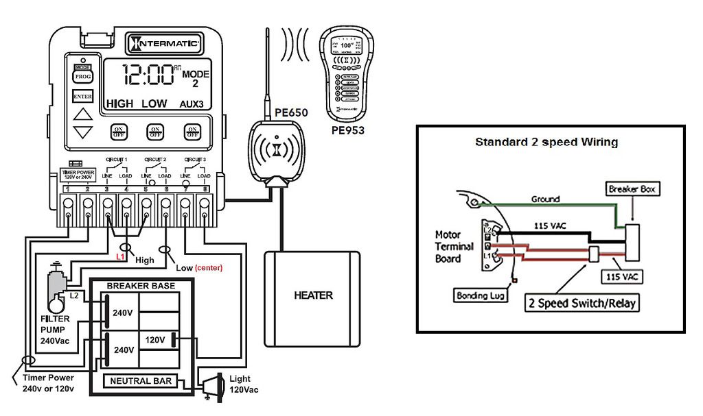
So after searching, I think the simplest way to automate my 2-speed pump is to change my standard timers (not sure the model) to the Intermatic digital P1353ME (unless there is something better, please let me know). Together with the schematic from the Whisperflo, I labeled wiring in the diagram above. (Please disregard the Light, Heater and the Wireless).Does it look right?

Also some questions:

The P1353ME only control 3 circuits but I need 4: 2 for 2-speed pump, 1 SWG and 1 for fountain pump. Currently I have 2 timers. 1 timer turns on/off both the 2-speed pump and the SWG simultaneously (I think with one circuit), and the fountain pump controller by the other timer. With the P1353ME, can I attach the SWG to the LOW circuit (circuit 2 on the diagram) of the pump to turn it on during low speed, and use the third circuit to control the fountain pump? If I was wrong about my existing pump/SWG timer has only one circuit then it's not possible.

Also, just curious, based on the schematic on the Whisperflo, does it mean low speed only uses 120v

Thx
 
Amati5,

If you look at your diagram on the right you can see that power is only applied to the center pin (low speed) OR L1 (high speed), but is not applied to both inputs at the same time. In your diagram on the left, you could turn on both inputs at the same time. Not a good idea. You really need a double throw relay like the one shown in your right diagram. Power goes through the top set of contacts to the center pin when the relay is de-energized through a set of Normally Closed contacts and through another set of Normally Open contacts to L1 when the relay is energized.

Your pump requires 220 volts in both low speed and high speed. The difference in speed is caused by which windings you connect the 220 volts to (Center or L1) and not the voltage.

Jim R.
 
Hi, Jim

I can see I could turn on both by faulty programming in the timer, if that's what you meant? I never thought of this. I found many people use this timer to control the 2-speed pump but never knew what involved.

So you're saying the relay, when not energized, close the top set circuit, and when energized, close the L1. That sounds like a STDT relay? Hmm...got to figure out how to wire the relay with the P1353ME.

Thx
 
Amati5,

Unfortunately, it is still going to take two of your three circuits to make it work.

1. Wire a Single Pole Double Throw (SPDT) relay just like in your right hand diagram. At this point your pump would run on low forever.

2. To turn the pump on and off run the power going into the common relay input through one of the three N/O contacts in the timer, say circuit 1. Now you can turn the pump on and off with the timer, but it will still only run on low speed.

3. Run the voltage that will control the relay (Easiest thing would be to use a relay with a 115 VAC coil) through the N/O contacts on a second timer circuit, say circuit 2. Now you can select low or high speed.

All timer circuits off, pump is off. Circuit one on, pump runs at Low speed. Circuit one and circuit two on, pump runs at High speed. Circuit two on by itself, pump is off.

Jim R.
 
Jim, that is very clever. I really appreciate that. Can't wait for the temp to cool down here to do some work and save me some $. Wonder if other people who use this timer do the same method.

Edit: oh, by the way, is it possible to "pigtail" the SWG to the circuit 1 ?

Thx
 
I have the Intermatic PE653RC Wireless Control System, uses almost the same setup.. It works really well and has timers built in for all 5 connections. the RF signal/wifi works about 50 feet away through 2 walls, but will depend on your setup.

I called and worked with intermatic, they are awesome and know there equipment very well.. here is how I have mine set up..

1 is high speed
2 is low speed
3 is SWG
4 is empty
5 is pool lights..

you could tie the swg to run when 1 or 2 is on but then it will only run on high or low speed.. to do 220 you use 1 leg from the timer and the other leg from the breaker.. my swg does not like being switched that way and I had to use 110 for it. when connected to 3 you can set the time when it comes on and goes off, just make sure the pump is programmed to be on at the same time. I turn my pump on and wait 3 minutes before the swg turns on and the swg turns off 3 minutes before the end of pump time...

this timer will not let you run 1 and 2 on at the same time, when 1 is on and you hit 2, 1 turns off and 2 turns on. 3, 4, and 5 will turn on at the same time.


I am ok to have the SWG to run with Low since it's will be on 80% of the pump time. I like to do it this way to avoid any chance the SWG being on without the pump. Interesting that your timer turns on either 1 or 2 which eliminate the need for the relay. I have to figure out if this timer or the P1353ME with the relay will fit in my existing box.

I forgot something about my current set up which I might need to look into. Right now, my pump is controlled by the timer but also by a wall switch inside the house, one can not override the other so I don't think it's a standard 3-way wiring. If I hook up my P1353ME like Jim mentioned above (common goes to timer) which is completely the opposite to what I have now (switch leg goes to the timer), I don't if that is going mess up something.

Thx
 
Amati5,

My original remarks were based upon the schematic, as I have no direct knowledge of this particular timer. A quick look at the manual showed that the timer can be set to several different internal configurations.

Mode 1 – (Aux1, Aux2, Aux3)
The time switch is a 3-circuit switch with all three switches controlling auxiliary
devices.

Mode 2 – (Pump High, Pump Low, Aux3)
The time switch is a 2-circuit switch with the 1st & 2nd switch controlling a two-
speed pump. The 3rd switch is controlling any auxiliary device. All protection
associated with a two speed pump is pre-programmed into this mode.

Plus several other modes.

Mode 1 was how I "assumed" the unit would work, but Mode 2 is how you would configure it to operate a 2-speed pump without the addition of an SPDT relay.

Sorry for any confusion.

I'm puzzled by your pump being controlled by a switch inside the house. Is this a 220 volt switch? When it is shut off does all the power to the pump go to zero? Are you sure you have 220 volt power at the pad? Something just does not "smell" right. Where does the input power to your current timer come from? The circuit breaker panel or the house switch or ???

Jim R.
 
Jim, Thank you very much for the research on the P1353ME. It's a relief I don't need the relay because I have no room left for it in my box (which already has 2 timers) unless I have to mount another box with wires jumping over. This will make everything so much easier. I should have done the research myself but I was so happy to find out I don't need one of those fancy controller to control my 2 speed pump.

I can't remember if the switch in the house is 220v. The circuit breakers are all in one box with the 2 timers so I think I have 220 at the pad. The way the pump being wired right now (if remember correctly) is the common permanently hardwired to the circuit breaker and the other leg (from the pump's switch) is controlled by the timer. I think this means the switch in the house is just 120v and when I shut off the pool (at least at the timer), not all power is removed from the pump. I think the input power for timer is from the breaker panel, right below it. I hope that makes sense.
 
Amati5,

Sorry, but the smell just got worse.. :p

I'm sure it is just a terminology thing, but I'm still puzzled. If you think you've got it under control great.. If not, a couple of pictures of your current equipment pad electrical box showing the circuit breaker and timer wiring would be great.

Also. not sure about the price difference but if this were my project I'd seriously think about going with a five circuit system like Cowboycasey recommended. One timer to control everything.

Jim R.
 

Enjoying this content?

Support TFP with a donation.

Give Support
I am currious as which part puzzled you. The pool came with the house when we bought it and when i changed the pump, i kept the wiring the same. That was the first time i looked at a 220v being hooked up with the timer. It was actually interesting to see how the common leg was wired straight to the 120v and the other being controlled by the timer to turn on/off the pump. I am pretty sure it's how the pump being wired. I can see how it works like that. That is not common? I dont know this myself so please share your opinion. I am just not so clear how the house switch wired. I havent got time to sit down to draw out the circuit on paper yet. I think if i can keep the wiring of the new timer basically the same (common being connected straight to the 120v source) i can still have the house switch operated as before, but probably only on Low.

To complete the picture, I also have another pump for the spa which can be remotely turned on by pushing a rubber cap on the wall in the spa. This cap forces air into a tube which send pressure all the way to the another device where the other end of the tube plugged into to activate the pump. The only thing this cap is placed a little too low into the water and it's not sealed so water got in the tube and block the air. Now I have to walk over to the pad to blow air directly into the device to turn on the pump. I can eliminate this whole air thing and wire the spa pump into the 5th circuit and control wirelessly if I buy Casey' timer.


Thx
 
I'm sorry I'm late to the game.

In your diagram, that's exactly how that timer is supposed to be hooked up. I like breaking both hot legs, but it's common practice to only break one leg when controlling a 220 volt device through a timer.

It's also perfectly acceptable to run power for the swcg off of circuit 1 or 2, your choice. That leaves the third circuit open for whatever else you need.

Now for the switch in the house. You say that one cannot override the other? Does that mean that if you turn on the switch the timer cannot turn the pump off? Also if the timer has the pump running can the swtich turn it off? My guess is that it should be wired parallel to one speed of the pump, but I can't be sure without seeing it.

Thx for the input. Neither the timer or the house switch can turn each other off. But both can turn the pump on regardless of what the other is doing. I like the way it works, saving me a trip to the pad when I want to turn on the pump for the heater (heater also has a switch in the house) but I have to remember to turn it off. This is why I haven't considered a control unit yet because I can control everything (almost, except the speed of the pump, ...lol) from the house and every thing is mechanical, no breakdowns.
 
I assume the switch in the house can only run the pump one speed?
If so which speed does it run it?

It sounds like the switch is wired parallel to the timer, so that if either the timer or the switch is on the pump runs.

Hopefully there's more to it than that. If it's wired like that then there's a possibility of powering the high and low windings of the motor at the same time.
 
The house switch runs whatever speed set at the pump (by a toggle switch on the motor). It was wired for 1 speed pump originally. I can open up the box to find out exactly how it's wired.

What does that do when it powers high and low at the same time?
 
That makes sense. Since it was just for a single speed pump it can't power the high and low speeds at the same time as it just sends power to the main power feed to the pump.

When you add the timer to run both speeds you need to be very careful about running the pump with the switch in the house. Applying power to both windings at the same time will destroy the motor. You can prevent that from happening by installing a relay to kill the power to one speed whenever you turn the switch on, but you already said that you don't have any room.


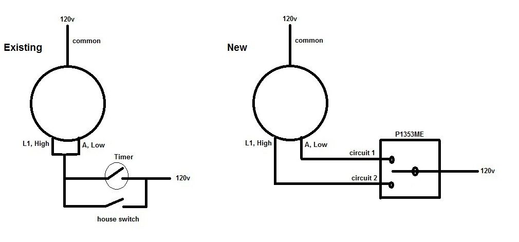
On the left is the existing wiring (I hope) and on the right is what seems like the wiring with the P1353ME should be. I think I am running to a dead end, not knowing what to do with my house switch. I can't figure out how to avoid the risk of running both high and low at the same time, even with the relay.
 
The diagram on the left is kinda correct.
The one on the right is correct if you're going to leave out the house switch.

If you want to run the pump on low using the house switch. I've attached a couple of diagrams. To run the pump on high just switch the relay and house switch to the other speed.

Parallel Sw-Rly & P1353.jpg
P1353ME, Relay, Manual Switch.jpg
 
Is this the same spdt we discussed above? Let me see if I understand how it works. It looks like pin 1 and 4 are normally close and:

-If either house switch or Timer Lo is on, it opens pin 1 and 4, and pump runs on low
-If Timer Hi turns on, pump runs on high
-If both Timer Hi and house switch is on, pumps runs on low (because 1 and 4 is open)
-And just curious, with this wiring, I think even without Mode 2, Lo and Hi still can't run together.

and If for any reason if the coil is not energized (loose connection at pin 2, etc...) when I turn on the house switch while Timer Hi is running, my pump will be toasted?...lol

Is that correct?

Thx
 
It's not the same as the spdt switch discussed above.

You have it pretty much correct, however you still need to configure the timer for 2-speed operation to ensure that circuit 1 & 2 can't be energized at the same time.

Yes that's basically correct, but the chance of that happening is small. And the thermal overloads should trip before it destroys the motor.
 

Enjoying this content?

Support TFP with a donation.

Give Support
Thread Status
Hello , This thread has been inactive for over 60 days. New postings here are unlikely to be seen or responded to by other members. For better visibility, consider Starting A New Thread.