I wasn't sure if I should bring this old post back to life http://www.troublefreepool.com/threads/80789-extension-cord-for-aquarite-chlorinator or start a new one, but I need to add about 6 feet to the standard 15' long cable that comes with the T-cell to make it reach the controller comfortably. Does anyone see any problems with splicing in 6' of appropriately-rated outdoor cable, maybe in a weather-tight enclosure of some kind? It would be a lot nicer to use the right mating connector, if anyone knows it.

Extend AquaRite T-Cell Cable
- Thread starter zamazing
- Start date
You are using an out of date browser. It may not display this or other websites correctly.
You should upgrade or use an alternative browser.
You should upgrade or use an alternative browser.
You could start here:
http://www.molex.com/molex/products/listview.jsp?query=&offset=0&filter=&fs=application%3Apower&npp=20&sType=z&autoNav=&path=cHome%23%23-1%23%23-1%7E%7Ef13%7C%7C3130%7E%7Enf35%7C%7C32&channel=Products&key=power_connectors
you'll need to look at the drawing links for the items you think would be what you need...the pics in the results are generic but the drawings are specific....if you could find the female connector, you could buy two and put jumpers in them and mount in a plastic box.
I had started doing that, but are you sure the connectors are made by Molex? There are other major connector manufacturers like Amphenol among others...
Sent from my iPad using Tapatalk
Sent from my iPad using Tapatalk
It looks like a molex connector to me...you could take it to an electronics component shop...This may not be close enough to you, but I'm sure theres other places like it...if you find someone that sells components and also deals in molex, they can help you fit it up.
Welcome To Greenbrook
Welcome To Greenbrook
Thanks for the suggestion. A Molex Rep visits my workplace regularly so I'll see if he can identify the connector.
Sent from my iPad using Tapatalk
Sent from my iPad using Tapatalk
Gilbee, you were right about this being a Molex connector. ")
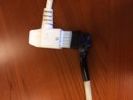
Yesterday, I grabbed a bag of random Molex connectors we use at work and, amazingly, one of them fits the Hayward Connector PERFECTLY!!
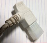
The Hayward connector is based on a standard Molex Mini-Fit Jr. Receptacle but it looks like Molex custom makes this connector for Hayward because the latching mechanism has been removed. I looked up the part and I've come up with the following Molex part number for the mating connector: 0469931011 (pdf attached) . The plug will require male pins (PN 0039000040) for the wires.
Yesterday, I grabbed a bag of random Molex connectors we use at work and, amazingly, one of them fits the Hayward Connector PERFECTLY!!
The Hayward connector is based on a standard Molex Mini-Fit Jr. Receptacle but it looks like Molex custom makes this connector for Hayward because the latching mechanism has been removed. I looked up the part and I've come up with the following Molex part number for the mating connector: 0469931011 (pdf attached) . The plug will require male pins (PN 0039000040) for the wires.
Attachments
it looks like Molex custom makes this connector for Hayward because the latching mechanism has been removed
lol, and with a pair of wire cutters, you too can custom make this connector! Glad you figured it out and posted the part numbers, that will prove useful for someone else...now go snag yourself a project box and make it pretty!
mguzzy
Gold Supporter
I'm curious.. why couldn't you solder the splice and insulate it with heat shrink or similar to make it water proof. There are similar products I've used for other low voltage splices that need to be water proof. That way you can use the original connector on the controller end.
I must admit I haven't reviewed the other thread yet.
Mark
I must admit I haven't reviewed the other thread yet.
Mark
I'm curious.. why couldn't you solder the splice and insulate it with heat shrink or similar to make it water proof. There are similar products I've used for other low voltage splices that need to be water proof. That way you can use the original connector on the controller end.
I must admit I haven't reviewed the other thread yet.
Mark
I think the idea is to leave the original cable from the cell uncut, in case he has an issue where Hayward needs to inspect the cell they can't kneejerk and blame the splice.
mguzzy
Gold Supporter
I think the idea is to leave the original cable from the cell uncut, in case he has an issue where Hayward needs to inspect the cell they can't kneejerk and blame the splice.
I thought of that right after I hit the "post" button... "warranty". Yeah, make an extension cable with a couple of Molex connectors.. especially if you have access to connectors. It looks like the accessory power connector from a PC power supply. Next time I am by my pool I will check.
They make connector housings for marine applications that would make your connection more water tight if you need it.
Mark
I think the idea is to leave the original cable from the cell uncut, in case he has an issue where Hayward needs to inspect the cell they can't kneejerk and blame the splice.
Exactly! Also, there are plenty of decommissioned T-Cell's out there with dead elements but perfectly functional cables. All you would need to make this extension is the cable from one of those units and the Molex mating plug and the male pins I mentioned in my post above.
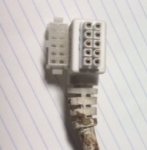
I figured I would continue to document this as I go along. Even though a 10-position connector is being used, the T-Cell only uses 6 of the 10 pins. There are two Black and two White wires that appear to supply the voltage to the T-Cell from the AquaRite controller. Looks like they're distributing the current across the two paths since the T-15 cells can draw over 6 AMPS. The Red and Blue wires are presumably carrying data (Water Temperature, Instant salt level, etc) back and forth between the controller and T-Cell.

Here are the Pin-outs to be used with the Molex 0469931011 mating plug:
BLACK 1 -> PIN 1
BLACK 2 -> PIN 2
WHITE 1 -> PIN 6
WHITE 2 -> PIN 7
RED -> PIN 8
BLUE -> PIN 10
The PIN numbers on the Molex connectors can be tricky so watch out.
Here are the Pin-outs to be used with the Molex 0469931011 mating plug:
BLACK 1 -> PIN 1
BLACK 2 -> PIN 2
WHITE 1 -> PIN 6
WHITE 2 -> PIN 7
RED -> PIN 8
BLUE -> PIN 10
The PIN numbers on the Molex connectors can be tricky so watch out.
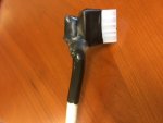
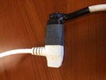
Here's the final product! I used a bunch of shrink-tubing and hot glue to make the mating connector as weatherproof as possible. I'm trying to avoid using any kind of project box or housing, so I'm hoping that the last piece of shrinkwrap around the two connectors will protect the wires from the elements.
Attachments

tooslo
0
My pool equipment is located at one end of the house and the control panel is at the other end (I did not put the pool in, it was there when I bought the house). Therefore, the standard 15' cable for the T-cell does not reach to the control panel. The existing T-cell had and additional 30' or so spliced in. I've since had to replace it and spliced in 30' myself to the new T-cell. Zamazing, your solution is much more elegant. What I've found is that the PPM reading on the control panel is about 1000 ppm low when compared to salt readings from local pool stores. Do you think that the added length of cable affects the PPM reading? Any ideas on a solution for this situation?
By the way Zamazing, you should sell those extension cables. Put me down for a 25 footer.
By the way Zamazing, you should sell those extension cables. Put me down for a 25 footer.
Tooslo, I don't think the additional length explains the Low salt reading because the communication between the panel and the T-cell occurs over an RS-485 link which can extend up to a thousand feet. The only real concern with a long extension is the voltage drop because of the high current draw of the t-cell. Are you sure your t-cell size is properly defined in your panel? That would explain the low salt reading.
Sent from my iPad using Tapatalk
Sent from my iPad using Tapatalk
HI All,
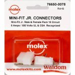
Using this thread I was also able to build a junction box to extend my T-Cell. I bought this Molex Connector Corporation 76650-0078 kit as I could not find the pieces separately. Followed the pin out from above, super easy.
Thanks again!

76650-0078 Molex Connector Corporation | Kits | DigiKey
Using this thread I was also able to build a junction box to extend my T-Cell. I bought this Molex Connector Corporation 76650-0078 kit as I could not find the pieces separately. Followed the pin out from above, super easy.
Thanks again!
76650-0078 Molex Connector Corporation | Kits | DigiKey
Attachments
hleapha
0
Looking at the image above of the wiring - Are the whites (neutral) and the Blacks (hot) directional or are the interchangeable? I wouldn't want to wire them backwards. I wouldn't think it would matter but when you take the cover off the T-cell, you can see how they each go into a separate side of the electronic they supply.
Looking at the image above of the wiring - Are the whites (neutral) and the Blacks (hot) directional or are the interchangeable? I wouldn't want to wire them backwards. I wouldn't think it would matter but when you take the cover off the T-cell, you can see how they each go into a separate side of the electronic they supply.
This is DC voltage (not AC) so the wires are definitely directional and should not be reversed.
Sent from my iPad using Tapatalk
Thread Status
Hello , This thread has been inactive for over 60 days. New postings here are unlikely to be seen or responded to by other members. For better visibility, consider Starting A New Thread.