I know some of you guys here are good with electronics and may be able to help me out a little. This is also on another forum so I will update here with replies from there that I feel are important to the project.
Basically, bought the scooter in '04-'05 and it worked great. Then a hidden fuse blew one day and I put it away for a year. I took it out, cut through half the wires, and then found the fuse. Rewired it so I had a push button on-off and that was it. Then the front fork fell off while I was riding it and I had a nasty crash. I put it away once again for a year and when I pulled it out the batteries were dead. I hooked up a 12v Deep Cycle(battery for our camper) and used that for a few days until the switch melted. I put it away again and got it out again yesterday because I want to use it to small scale test some Hybrid Systems.
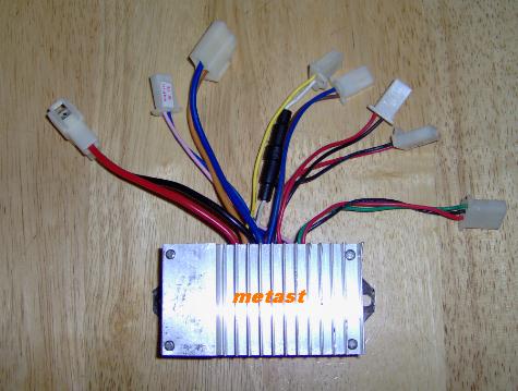
I'm going to get this thing going again back in it's original glory, but better. I ordered a new control module off eBay today. They are cheaper now($16.00) than a few years ago. Tomorrow hopefully I'll be buying 2 new 12v 12Ah maybe 17 Ah(motor is 24v) batteries to power the thing. Going by my old mileage, this should allow me to go about a mile. The math says I should be able to run at full throttle(motor draws 19amps) for about 1/2 hour, which sounds about right. My farthest friend (that I'd normally bike too) requires me to go 3 miles round trip. This is my target. This is why I'm building the Hybrid drive.
The hybrid drive is basically just a 2-stroke edger engine attached to a DC generator that will charge the batteries and power the motor when the batteries get low. As it is now I only have two big challenges to overcome. First is how to connect the engine and the generator together, and second is how to let the gen. charge the batts. without feeding the motor and control module 36v(I'm figuring if the batts are putting out near 24v and the gen. is another 13-14v that makes 36vdc, am I right in this thinking?).
Here are some pics.
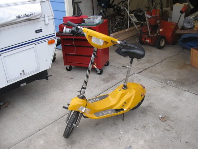
Scooter in current state.
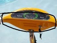
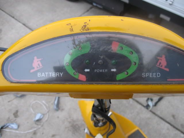
The dashboard that indicates power, speed, battery, and turn signals.
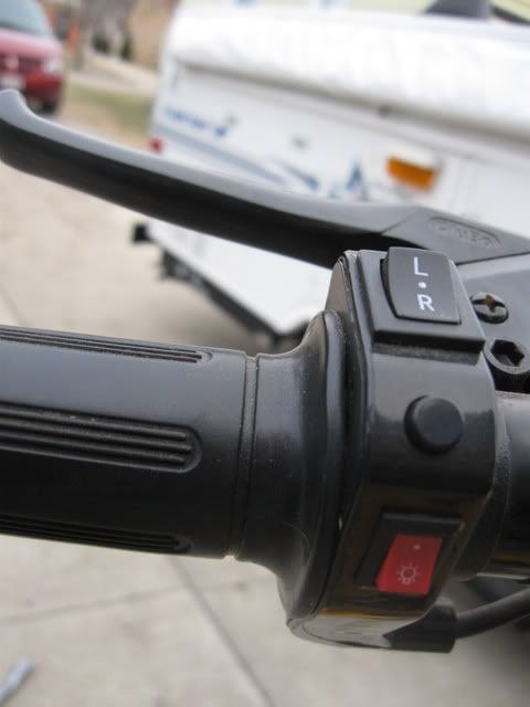
This is the left handle.It contains switches for the headlight, blinkers, horn, and rear drum brake/brake light.
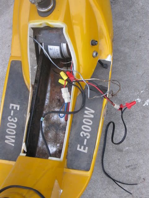
This is where the batteries used to go and where the engine and gen. will go. You can see some of my old wiring here.
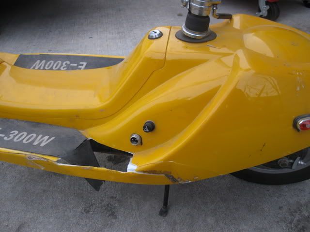
This is the worst cracked plastic,well actually, this is pretty much all if it. Is there a way to repair this to look like new? or even decent looking? What happened was it tipped over once and cracked the vertical strip piece under the footrest. Well, me stepping on it eventually cracked more of it.
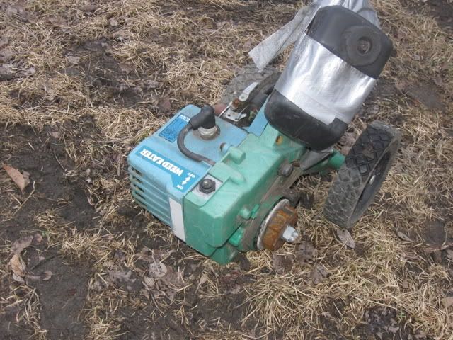
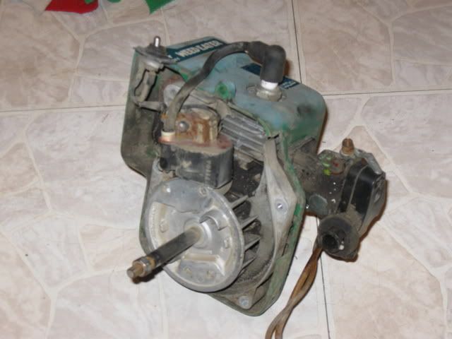
This is the engine, first on the edger, then how it will be in the scooter.
This is the gen. that I'll be using.
See, I need to connect those two shafts directly somehow. The engine one is smaller, and I can't use the threaded part(which goes to where the nut is) because I need to cut it off to make the assembly fit into the space. My dad says I should build up the smaller(engine) shaft with sleeves until it's even with the other shaft then just use another sleeve with two set-screws to hold them together. This plan sounds OK I just need to know HOW to get the sleeves to hold tight on the shaft and not spin, any ideas???
I think that's about it for now.
ALL INPUT IS APPRECIATED!
Adam
Basically, bought the scooter in '04-'05 and it worked great. Then a hidden fuse blew one day and I put it away for a year. I took it out, cut through half the wires, and then found the fuse.
Rewired it so I had a push button on-off and that was it. Then the front fork fell off while I was riding it and I had a nasty crash. I put it away once again for a year and when I pulled it out the batteries were dead. I hooked up a 12v Deep Cycle(battery for our camper) and used that for a few days until the switch melted. I put it away again and got it out again yesterday because I want to use it to small scale test some Hybrid Systems.I'm going to get this thing going again back in it's original glory, but better. I ordered a new control module off eBay today. They are cheaper now($16.00) than a few years ago. Tomorrow hopefully I'll be buying 2 new 12v 12Ah maybe 17 Ah(motor is 24v) batteries to power the thing. Going by my old mileage, this should allow me to go about a mile. The math says I should be able to run at full throttle(motor draws 19amps) for about 1/2 hour, which sounds about right. My farthest friend (that I'd normally bike too) requires me to go 3 miles round trip. This is my target. This is why I'm building the Hybrid drive.
The hybrid drive is basically just a 2-stroke edger engine attached to a DC generator that will charge the batteries and power the motor when the batteries get low. As it is now I only have two big challenges to overcome. First is how to connect the engine and the generator together, and second is how to let the gen. charge the batts. without feeding the motor and control module 36v(I'm figuring if the batts are putting out near 24v and the gen. is another 13-14v that makes 36vdc, am I right in this thinking?).
Here are some pics.
Scooter in current state.
The dashboard that indicates power, speed, battery, and turn signals.
This is the left handle.It contains switches for the headlight, blinkers, horn, and rear drum brake/brake light.
This is where the batteries used to go and where the engine and gen. will go. You can see some of my old wiring here.
This is the worst cracked plastic,well actually, this is pretty much all if it. Is there a way to repair this to look like new? or even decent looking? What happened was it tipped over once and cracked the vertical strip piece under the footrest. Well, me stepping on it eventually cracked more of it.
This is the engine, first on the edger, then how it will be in the scooter.
This is the gen. that I'll be using.
See, I need to connect those two shafts directly somehow. The engine one is smaller, and I can't use the threaded part(which goes to where the nut is) because I need to cut it off to make the assembly fit into the space. My dad says I should build up the smaller(engine) shaft with sleeves until it's even with the other shaft then just use another sleeve with two set-screws to hold them together. This plan sounds OK I just need to know HOW to get the sleeves to hold tight on the shaft and not spin, any ideas???
I think that's about it for now.
ALL INPUT IS APPRECIATED!
Adam